


10 11
500Sr Recumbent Assembly Instructions
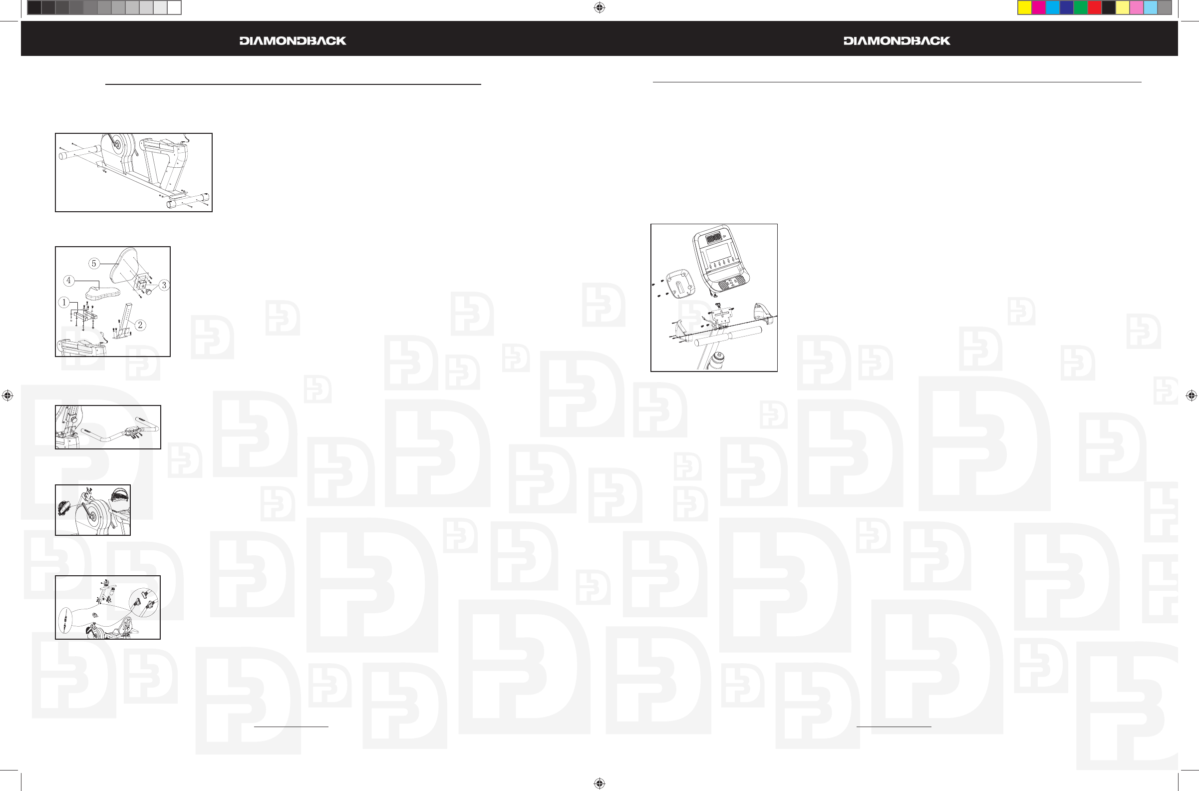
500Sr Recumbent Assembly Instructions (Continued)
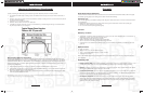
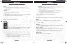
three screws and make sure that the two top holes are light up with the holes on the receptor.
Snap console mast cover into top of sidecase.4.
Insert and tighten two M8 x 16mm bolts and fl at washers onto the two holes above the console mast 5.
cover using a 6mm Allen wrench.
Place the bottle holder on the console mast. Insert and tighten two M5 x 15mm screws using a Phil-6.
lips screwdriver.
Snap the water bottle into the bottle holder.7.
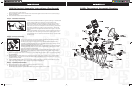
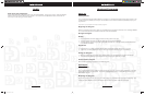
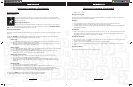
Step 6: Console Assembly
Insert the ends of the main wiring harness and hand pulse wiring harness, 1.
trough the opening of the rear console cover.
Connect both plugs, from the main wiring harness and hand pulse wiring 2.
harness, to the plug receptors on the backside of the console taking care
to install correctly (see plug alignment marks).
WIRING HARNESS INSTALLATION HINT: Any excess wiring must be care-
fully inserted (“stored”) back into the console mast before installing the
console onto the console mounting plate.
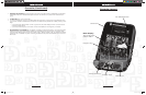
Attach the console to the console mounting plate with the four M5 x 3.
10mm screws on the top and bottom holes of the mounting plate using a
Phillips screwdriver.
Attach the rear console cover to the back of the console using four M5 x 4.
10mm screws using a Phillips screwdriver.
Attach the right console plastic mount hood to console mast using one 5.
M5 x 14mm bolt and Phillips screwdriver. The cover should sit above the
plastic handlebar cover and below the mounting bracket for the console.
Attach the left console plastic mount hood to console mast using one M5 x 14mm bolt then to the 6.
right cover using three M3 x 14mm screws and a Phillips screwdriver.
Step 7: Transformer Assembly
Plug transformer into plug receptor located on the front of the unit.1.
Plug the transformer into power outlet.2.
NOTE: Be sure to use the right transformer for your power outlet, 110V or 220V.
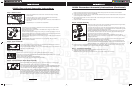
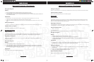
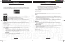
Step 1: Stabilizer Bars
Place rear stabilizer bar under rear main frame body and align 1.
screw holes.
Insert two M8 x 75mm bolts into the stabilizer bar all the way 2.
through and into the holes on the frame
Secure the stabilizer bar using an M8 nut and a curved washer on 3.
each bolt.
Repeat steps 1 – 3 to attach front stabilizer.4.
Step 2: Seat Assembly
Install seat mount bracket to seat slide on the seat track using four M8 x 1.
16mm bolts and four washers.
Install seat support to seat slide on the seat track using four M8 x 16mm 2.
bolts and four washers.
Loosen the seat back locking pin by turning it counter-clockwise 1-2 turns. 3.
Install the seat back mount bracket by sliding it onto the back support tube,
pulling the seat pin out until a suitable hole is found.
Install the seat pad on seat mount bracket using four M8 x 45mm bolts and 4.
four washers
Install the seat back pad on seat back mount bracket using four M8 x 5.
16mm bolts and washers.
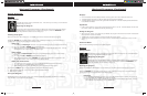
Step 3: Rear Handle Bar
Install rear handle bar to the bracket on the rear of the back support tube us-1.
ing four M8 x 16mm and four fl at washers
Plug in the HR pulse harness coming out of the plastic body to the receptor on 2.
the back of the handle bar.
Step 4: Pedals Assembly
Use a 15mm open-end wrench to fi rmly affi x the pedals to the cranks.1.
The left and right pedals are different and are denoted as right or left (R or L) on the 2.
top & bottom of each pedal.
NOTE: Left pedal threads counterclockwise.
Retighten cranks after approximately 10 hours of use.3.
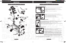
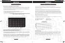
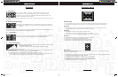
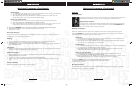
Step 5: Console Mast & Water Bottle Assembly
Remove console mast plastic cover from the unit's body by un-snapping it.1.
Slide console mast cover onto bottom of console mast2.
Connect both the main wire harness and the hand pulse harness in the main 3.
frame to the two wire harnesses in the bottom of the console mast, taking
care to install correctly. (See plug alignment marks)
Install the console mast by sliding it into the console mast receptor while gen-4.
tly pulling the wiring harness. This will keep the slack out of the harness so the
wires will not get pinched and short out. Insert and tighten three M8 x 16mm
bolts, one fl at washer on each side and a curve washer on the front using a
6mm Allen wrench. Be sure not to pinch wire harness while tightening these
500Ub.Sr OM R1.indd 10-11500Ub.Sr OM R1.indd 10-11 6/11/2008 9:54:24 AM6/11/2008 9:54:24 AM