


8 9
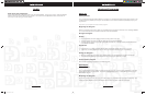
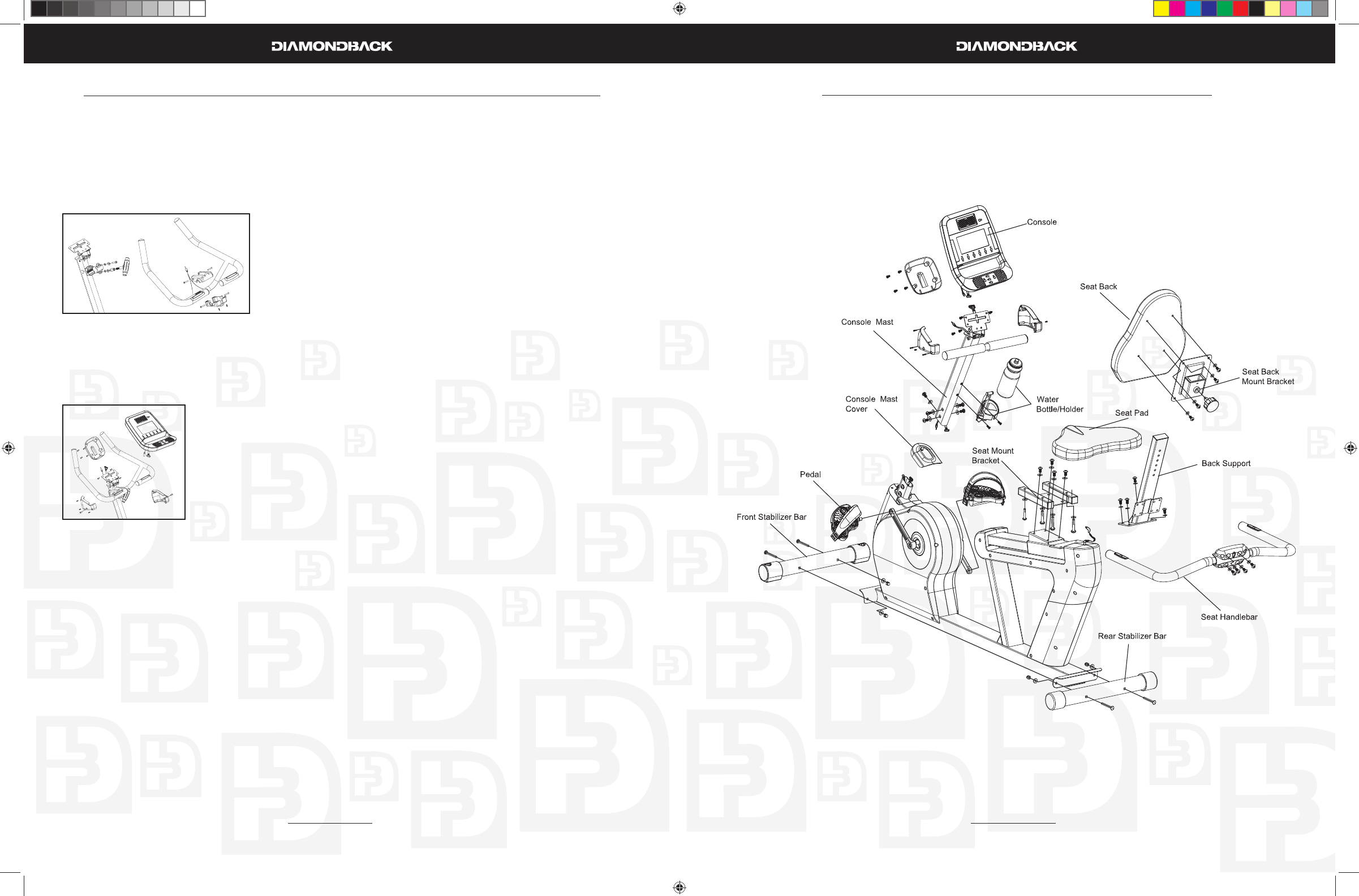
500Sr Recumbent Assembly Drawing
500Ub Upright Assembly Instructions (Continued)
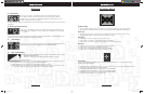
cover using a 6mm Allen wrench.
Place the bottle holder on the console mast. Insert and tighten the two M5 x 12mm screws using a 7.
Phillips screwdriver.
Snap the water bottle into the bottle holder.8.
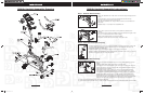
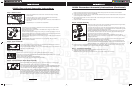
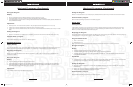
Step 5: Handlebar Assembly
Insert the hand pulse harness through the opening on the left side 1.
of the console mast and out the top of the console mast.
Set the handlebar in place and secure it using a clamp, an M7 x 2.
P1.0 x 30mm bolt with a spring washer and fl at washer on top
hole of the clamp and a T-shape Knob with a bushing, a fl at wash-
er and spring washer on bottom hole of the clamp. As the bolt
and T-shape knob are tightened leave the same gap on top and
bottom.
Install the handlebar top and bottom covers by attaching them to 3.
each other from the opening in the bottom of the bottom cover
using two M3 x 14mm Screws and one M5 x 25mm on each side
of each cover.
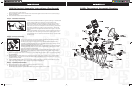
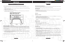
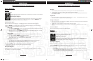
Step 6: Console Assembly
Insert the ends of the main wiring harness and hand pulse wiring harness, 1.
trough the opening of the rear console cover.
Connect both plugs, from the main wiring harness and hand pulse wiring 2.
harness, to the plug receptors on the backside of the console taking care to
install correctly (see plug alignment marks).
WIRING HARNESS INSTALLATION HINT: Any excess wiring must be carefully
inserted (“stored”) back into the console mast before installing the console
onto the console mounting plate.
Attach the console to the console mounting plate with the four M5 x 10mm 3.
screws on the top and bottom holes of the mounting plate using a Phillips
screwdriver.
Attach the rear console coverl to the back of the console using four M5 x 10mm screws using a Phil-4.
lips screwdriver.
Attach the right console plastic mount hood to console mast using one M5 x 14mm bolt and Phil-5.
lips screwdriver. The cover should sit above the plastic handlebar covers and below the mounting
brackter for the console
Attach the left console plastic mount hood to console mast using one M5 x 14mm bolt then to the 6.
right cover using three M3 x 14mm screws and a Phillips screwdriver.
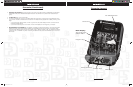
Step 7: Transformer Assembly
Plug transformer into plug receptor located on the rear of the unit1.
Plug the transformer into power outlet.2.
NOTE: Be sure to use the right transformer for your power outlet, 110V or 220V.
500Ub.Sr OM R1.indd 8-9500Ub.Sr OM R1.indd 8-9 6/11/2008 9:54:21 AM6/11/2008 9:54:21 AM