11
1 1 5 0 S E R I E S O W N E R’ S M A N U A L
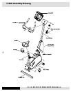
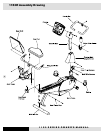
1150EL Assembly Instructions
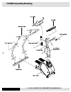
Console Mast Assembly
1. Connect main wire harness at the bottom of console mast to
wire harness at the front of frame.
2. Slide console mast into console mast receptor at front end of
frame. Be careful not to pinch the wire harness.
3. First, attach console mast to frame at upper hole-locations on
both sides using two M10x20mm screws with their washers and
an Allen wrench. Do not tighten too much yet.
4. Next, attach console mast at lower hole-locations on both sides
of console mast receptor. NOTE: there are three holes on either
side to choose from. The middle hole is for average-sized users
and will be suitable for most. The hole closest to the footpads is
for taller users, and the hole farthest from the footpads is for
shorter users. Choose the desirable hole and tighten the screws
by using M10x20mm screws with their washers and an Allen
wrench. Then tighten the two screws of upper holes of console
mast receptor.
NOTE: In order to avoid console mast loosen up after a while of
use. Please check and tighten these screws as often as possible.
5. Place console mast cover in the front of console mast. Insert
and tighten four M5x12mm screws with a Phillips screwdriver.
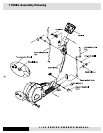
Handrail Assembly
1. Attach right handrail to the console mast at the right handrail
axle using the set-screw collar. Tighten the set-screw of the right
handrail set screw collar by using an Allen wrench.
2. Next, attach the right handrail to the bottom of the right steparm.
Insert the handrail/steparm axle through the holes in the steparm
and through the tube at the bottom of handrail. Insert a
M8x20mmscrew with washer into steparm axle and tighten it
using an Allen wrench and an open-end wrench on each side.
3. Assemble left handrail the same way.
4. Attach both steparm/handrail covers using M5x25mm screws
each and a Phillips screwdriver.
5. On either side of water bottle cover, attach the handrail covers
to each other around the handrails. Then use the two M4x 40mm
screws and nuts on each side and tighten them with a Phillips
screwdriver.
Handlebar Assembly
1. Insert the hand pulse harness through the opening of the con-
sole mast and out of the console mounting plate.
2. Assemble the handlebar onto the mount and insert and tighten
the four M8x12mm screws using an Allen wrench. Be sure not to
pinch the hand pulse harness during this procedure, as this will
damage the electronic console.
Console Assembly
1. Connect both plugs, from main wire harness and hand pulse
harness, to the plug receptors on the backside of the console,
taking care to install correctly (see plug alignment marks).
WIRING HARNESS INSTALLATION HINT: Any excess wiring
must be carefully inserted (“stored”) back into the console
mast before installing the console onto the console mount-
ing plate.
2. Fasten the console to the console mounting plate with the four
M5 x 12mm screws and washers using a Philips screwdriver.
Transportation Wheel Assembly
1. Insert both Transportation wheel’s sleeves into stabilizer bar,
making sure the screw hole is lining up with the hole of the sta-
bilizer bar. Tighten both inner bushings with its screw using a
Philips screwdriver.
2. Assemble Transportation wheels onto wheel sleeves until the
clips are engaged. See assemby drawings for details.
Waterbottle
1. Insert the water bottle into the water bottle holder.
Leveling Pad
1. Adjust all leveling pads, located on the front-bottom of the main
frame, to ensure your equipment is leveled with floor.


