


WT2240 Electrode Container, to
preserve the flux coating.
● The welder control panel contains
information regarding proper input
voltage and amperage. Follow the
specifications on the welder front
panel.
● The receptacle used for the welder
must be properly grounded and the
welder must be the only load on the
power supply circuit. Refer to the
Circuit Amps chart under
Specifications for correct circuit
capacity.
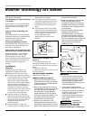
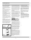
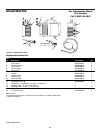
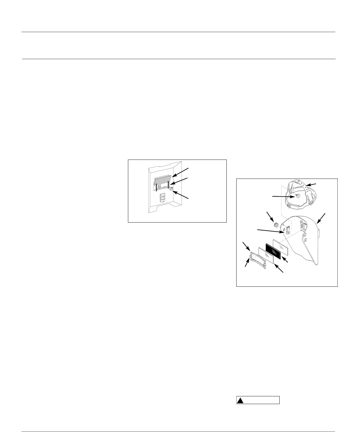
HAND SHIELD ASSEMBLY (See
Figure 4)
1. Cut retainer stiffeners and
detachable handle away from shield.
Trim the excess plastic to remove sharp
edges.
2. Insert the filter lens.
3. Attach the stiffeners over the pins on
the lens retainers.
4
Operating Instructions and Parts Manual
Inverter Technology Arc Welder
Protection Association, Batterymarch
Park, Quincy, MA 02269
Safe Handling of Compressed Gases
in Cylinders
CGA Pamphlet P-1, from Compressed
Gas Association, 1235 Jefferson Davis
Highway, Suite 501, Arlington, VA
22202
Code for Safety in Welding and
Cutting
CSA Standard W117.2, from Canadian
Standards Association, Standards Sales,
178 Rexdale Boulevard, Rexdale,
Ontario, Canada M9W 1R3
Cutting And Welding Processes
NFPA Standard 51B, from National Fire
Protection Association, Batterymarch
Park, Quincy, MA 02269
Safe Practices For Occupational And
Educational Eye And Face Protection
ANSI Standard Z87.1, from American
National Standards Institute, 1430
Broadway, New York, NY 10018
Refer to the Material Safety Data Sheets
and the manufacturers instructions for
metals, electrodes, coatings and
cleaners.
Installation
LOCATION
Selecting the proper location can
significantly increase performance,
reliability and life of the arc welder.
● For best results locate the welder in
an environment that is clean and dry.
Avoid locations exposed to high
temperature, high humidity, dust
and corrosive fumes. High humidity
causes moisture condensation on
electrical components. Moisture can
contribute to corrosion and short
electrical components. Dust and dirt
in the welder retain moisture and
increase wear of moving parts.
● Place the welder in an area that
provides at least twelve inches (305
mm.) of ventilation space at both the
front and rear of the unit. Keep all
obstructions away from this
ventilation space.
● Store electrodes in a clean, dry
location with low humidity, such as
www.chpower.com
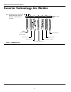
MODEL WT1000 (See Figure 5)
1. Remove the lens retainer from the
face shield with a regular screwdriver
by prying against the shield and post
of the lens retainer.
2. Remove the protective film covering
from both sides of each lens cover. Put
one clear lens cover on each side of
the shaded lens. Place these three
lenses together into the face shield
and secure with the lens retainer. The
lens retainer should snap into the
second notch in the face shield.
3. Position one of the holes in the
adjustment arm over the pins which
are located in the ear area of the face
shield. These adjustment arms control
Figure 5 – Helmet Assembly
Headgear
Face Shield
Shaded Lens
Clear Lens Cover (2)
Post
Lens Retainer
Adjustment
Arm (2)
Tension Nut (2)
Stud Screw (2)
WELDING HELMET ASSEMBLY
(Promotional Models Only)
Lens
Lens
Retainer
Retainer
Stiffener
Figure 4 – Hand Shield
the closeness of fit and can be easily
repositioned if necessary.
4. Position the headgear inside the face
shield. Assemble the helmet by
inserting the stud screw through the
headgear and shield into the tension
nut as shown. Do not tighten tension
nut completely.
5. Trial fit the welding helmet. Adjust
headgear ratchet band to a
comfortable position and lower the
face shield. If the shield is too far or
too close to the face, use a different
hole in the adjustment arm. Adjust the
tension nuts so that helmet can be
easily lowered over the face by
nodding the head.
Operation
1. Be sure to read, understand, and
comply with all precautions in the
General Safety Information section.
Be sure to read the entire section
entitled Welding Guidelines prior to
using this equipment.
2. Turn welder off and plug into
appropriate receptacle: 115v-20 amp
3. Verify that the surfaces of metals to
be joined are free from dirt, rust,
paint, oil, scale or other
contaminants. These contaminants
make welding difficult and cause
poor welds.
All persons
operating this
equipment or in the area while
equipment is in use must wear
protective welding gear including: eye
!
WARNING