


11
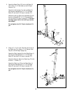
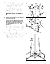
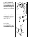
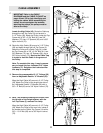
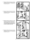
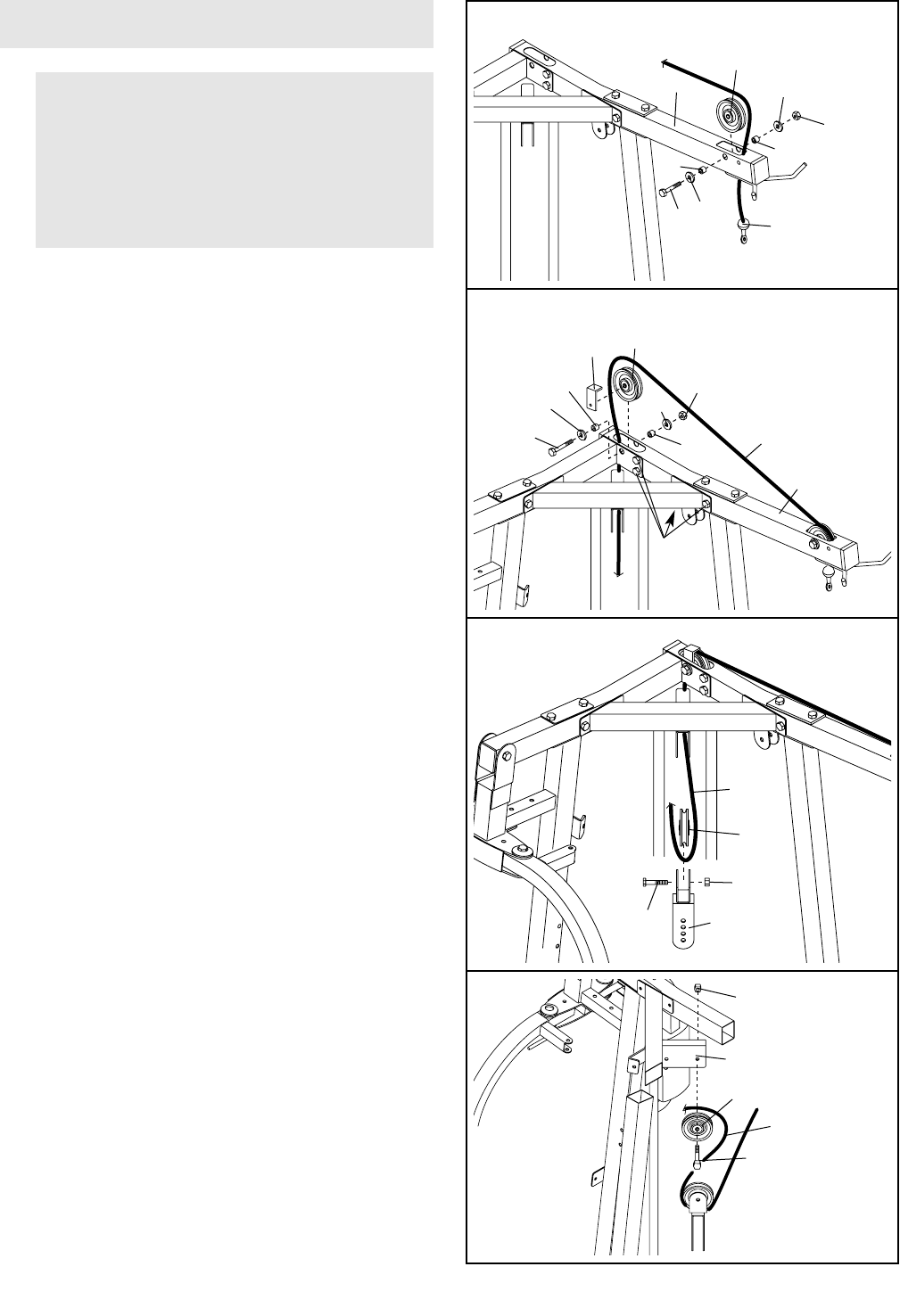
20. Note: The following drawings are shown from
the left side of the weight system, with the
Left Top Frame (3) removed for clarity.
Wrap the High Cable (45) around a 3 1/2” Pulley
(38). Attach the Pulley at the rear hole, inside of
the bracket on the Center Top Frame (14) with a
3/8” x 1 3/4” Bolt (66) and a 3/8” Nylon Locknut
(70).
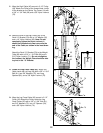
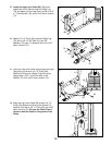
17.
Locate the High Cable (45). Route the Cable up
through the Left Top Frame (3) and around a
3 1/2” Pulley (38). Attach the Pulley inside the Top
Frame with a 3/8” x 2 3/4” Bolt (81), two 3/8”
Washers (75), two 1/2” Spacers (34), and a 3/8”
Nylon Locknut (70).
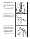
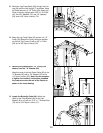
18. Route the High Cable (45) around a 3 1/2” Pulley
(38) and down through the Left Top Frame (3).
Attach the Pulley and a Cable Trap (91) inside
the Top Frame with a 3/8” x 2 3/4” Bolt (81), two
3/8” Washers (75), two 1/2” Spacers (34), and a
3/8” Nylon Locknut (70). Be sure the Cable Trap
is turned to hold the Cable in the groove of
the Pulley.
Note: To complete this step, it may be neces-
sary to loosen the four indicated 5/16” Nylon
Locknuts (71). Retighten the Locknuts when
this step is completed.
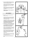
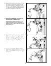
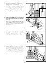
19. Remove the preassembled 3 1/2” Pulleys (38)
from an Adjustable Double “U”-Bracket (56).
Wrap the High Cable (45) around a 3 1/2” Pulley
(38). Attach the Pulley to the single hole side of
the Adjustable Double “U”-Bracket (56) with a
3/8” x 2” Bolt (62) and a 3/8” Nylon Locknut (70).
38
45
75
70
81
75
34
3
34
17
3
34
75
34
75
81
38
70
71
91
45
18
70
56
38
62
45
19
38
66
70
45
14
20
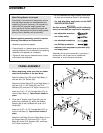
CABLE ASSEMBLY
IMPORTANT: Refer to the CABLE
DIAGRAMS and the CABLE ID CHART on
pages 24 and 25 for help identifying and
routing the cables. While assembling the
cables, do not overtighten the locknuts
attaching the pulleys; the pulleys must be
able to turn freely.