14
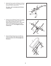
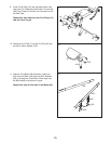
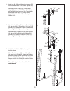
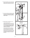
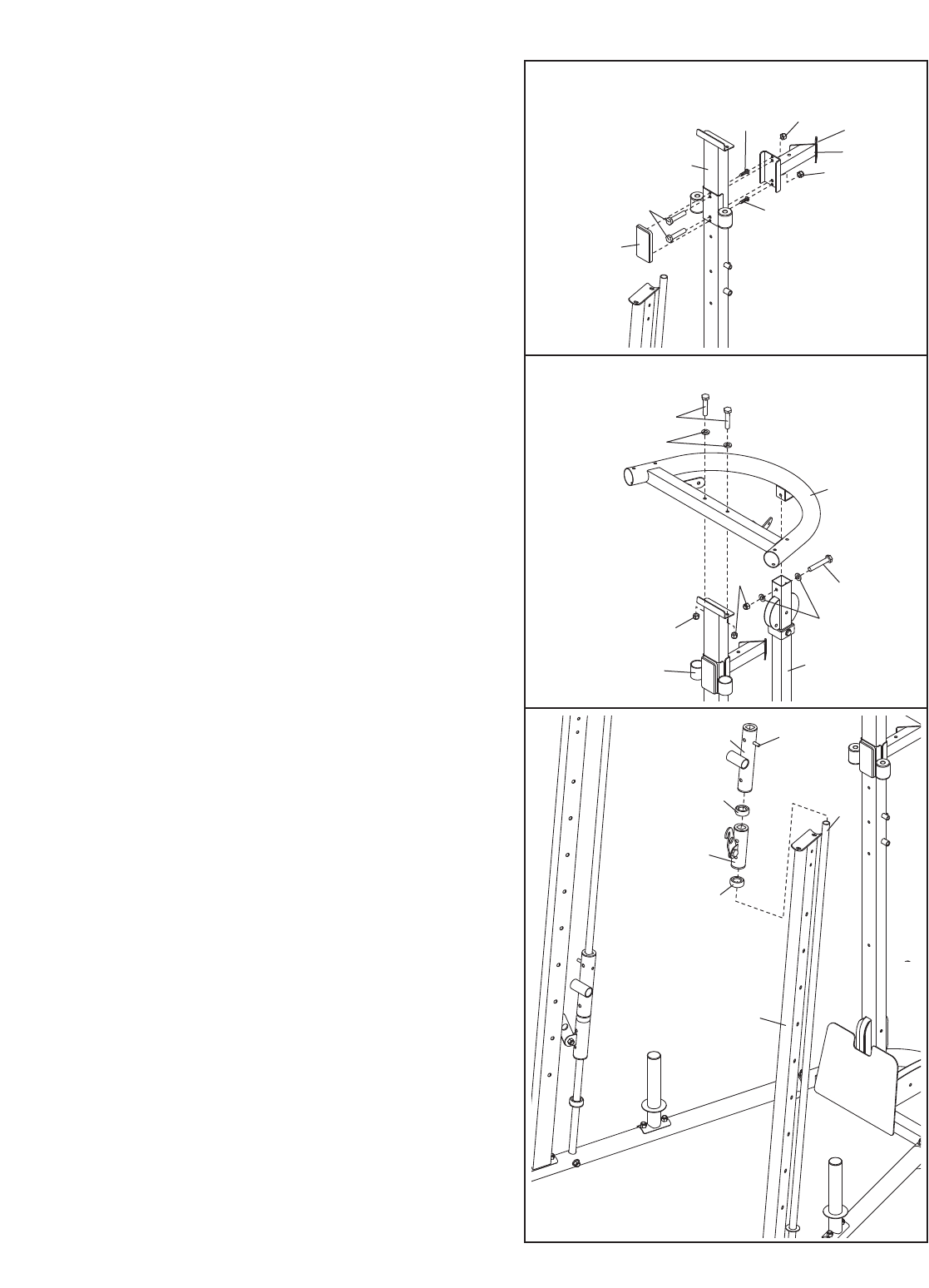
20. Attach the Rear Frame (31) to the Center Upright
(29) with two M10 x 70mm Bolts (116), two M10
Washers (96), and two M10 Nylon Locknuts (94).
Do not tighten the Nylon Locknuts yet.
Attach the Rear Frame (31) to the Rear Upright
(30) with an M10 x 65mm Bolt (124), two M10
Washers (96), and an M10 Nylon Locknut (94).
Do not tighten the Nylon Locknut yet.
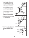
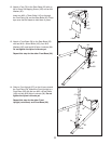
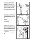
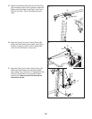
21. Identify the Left Guide (38) that has a pin in the
location shown.
Slide a Guide Bumper (90) and a Safety Spotter
(40) onto the left Guide (28). Insert the hook on
the Safety Spotter into an adjustment hole in the
Front Upright (27). Then, slide another Guide
Bumper and the Left Guide (38) onto the Guide.
Repeat this step for the other side of the
weight bench.
20
21
31
30
96
1
16
124
29
94
96
94
38
90
40
28
90
Pin
27
1
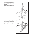
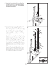
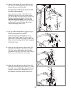
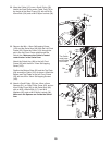
9. Insert two M4 x 60mm Self-tapping Screws (122)
into the smaller holes in the Center Upright (29).
Attach the Center Frame (51) to the Center
Upright (29) with two M10 x 70mm Bolts (116)
and two M10 Nylon Locknuts (94). Then, attach
t
he Support Plate Cover (71) to the Center
Upright with the two M4 x 60mm Self-tapping
S
crews (122).
1
9
29
51
116
9
4
94
122
122
Tab
71


