


7
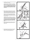
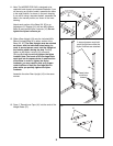
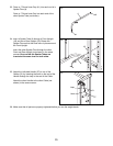
3. Press 20mm x 40mm Inner Caps (44) into the ends
of both Backrest Tubes (25).
Lubricate an M10 x 152mm Bolt (11). Attach the
Backrest Tubes (25) to the Bench Frame (49) with
the Bolt, two M10 Washers (15), and an M10 Nylon
Locknut (14). The Backrest Brackets must be ori-
ented as shown. Do not overtighten the Nylon
Locknut; the Backrest Brackets must be able to
move freely.
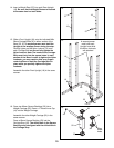
4. Slide the Adjustment Bracket (26) onto the Bench
Frame (49). See the inset drawing. The guide rod
inside the Adjustment Bracket must be on the indi-
cated side of the welded tube in the Bench Frame.
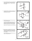
Align one set of holes in the Adjustment Bracket
(26) with the hole in the Bench Frame (49). Insert
the “L” Pin (46) through the Adjustment Bracket and
the Bench Frame.
Lubricate an M10 x 152mm Bolt (11). Attach the
Adjustment Bracket (26) to the Backrest Tubes (25)
with the Bolt, two Adjustment Bracket Spacers (50),
and an M10 Nylon Locknut (14). Do not overtight-
en the Nylon Locknut; the Backrest Brackets
and Adjustment Bracket must be able to move
freely.
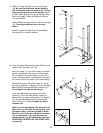
5. Attach the Backrest (29) to the Backrest Tubes (25)
with four M6 x 48mm Screws (35) and four M6
Washers (42).
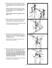
6. Attach the Seat (34) to the Bench Frame (49) with
the M6 x 60mm Screw (16), two M6 x 16mm
Screws (17), and three M6 Washers (42).
6
3
4
5
11—Lubricate
15
25
44
15
14
44
Welded
Tube
Lubricate—11
25
50
14
46
46
49
49
Guide
Rod
42
42
35
35
25
29
42
34
49
42
17
16
49
26
26