


GB
3
OWNER'S MANUAL
•
F20
adjustments other than those described
in this guide. Everything else must
be left to someone familiar with the
maintenance of electromechanical
equipments and authorised under the
laws of the country in question to carry
out maintenance and repair work.
SAVE THIS INSTRUCTION MANUAL
WELCOME TO THE WORLD OF TUNTURI
EXERCISING!
Your choice shows that you really want to invest in
your well being and condition; it also shows you
really value high quality and style. With Tunturi
Fitness Equipment, you’ve chosen a high quality,
safe and motivating product as your training
partner. Whatever your goal in training, we are
certain this is the training equipment to get you
there. You’ll find information about using your
exercise equipment and what makes for efficient
training at Tunturi’s website at www.tunturi.com.
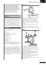
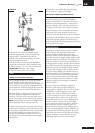
ASSEMBLY
Start by unpacking the equipment and check that
you have the following parts:
1. Frame
2. Rear support
3. Plastic covers for front support (2 pcs)
4. Front support
5. Pedals (2 pcs)
6. Seat support
7. Seat
8. Handlebar support
9. Handlebar
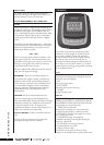
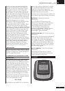
10. Console
11. Console back cover
12. Assembly kit (contents marked with in the
spare part list): keep the assembly tools, as you may
need them e.g. for adjusting the equipment.
If necessary, please contact your dealer with the
model, equipment serial no. and spare part no.
of the missing part. You’ll find a spare part list at
the back of this guide. The packaging includes a
silicate bag for absorbing moisture during storage
and transportation. Please dispose of the bag once
you have unpacked the equipment. The directions
left, right, front and back are defined as seen from
the exercising position.
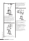
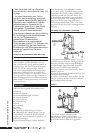
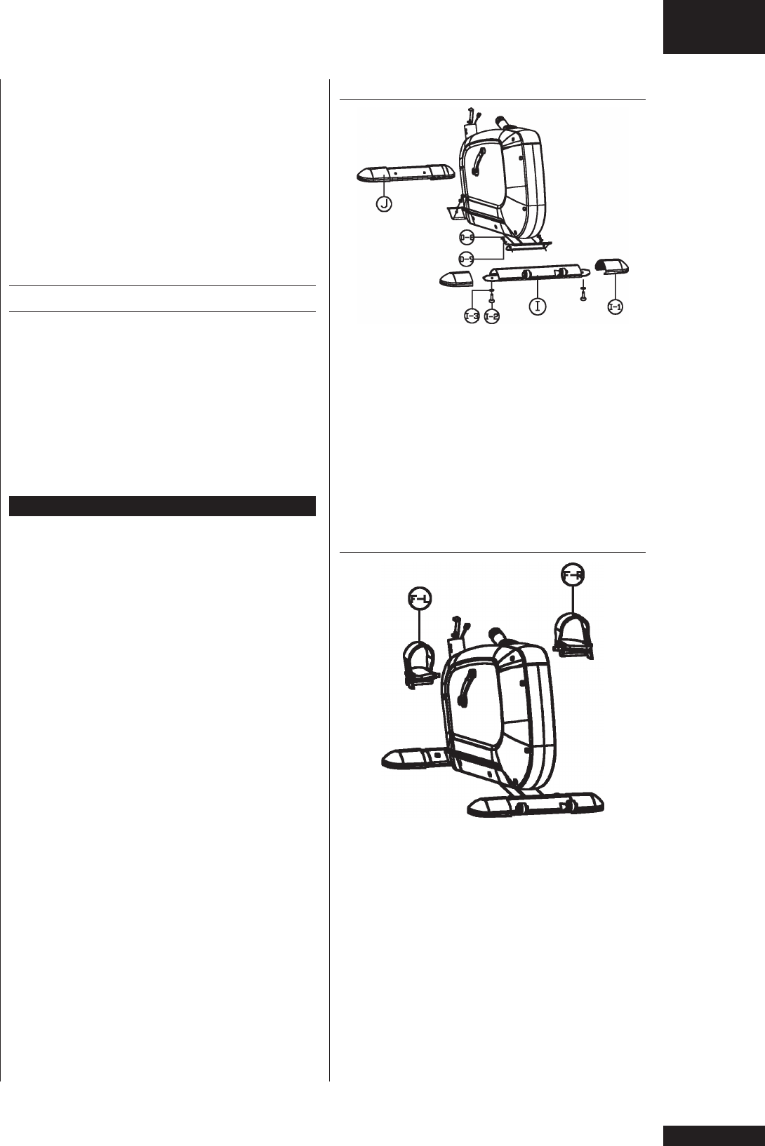
SUPPORT FEET
1. Push the grey plastic covers in place at both
ends of the rear support so that the support
retainers are aligned with the oval holes of the
covers. Fasten under the support with adjustment
screws.
2. Place the rear support underneath the rear part
of the frame.
3. Fasten the rear support with hex screws and
washers.
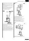
4. Place front support underneath the front part of
the frame and fasten with hex screws and washers.
PEDALS
1. The pedals are distinguished by the markings
R (= right) and L (= left) on their shafts. Fasten
the right pedal to the right pedal crank turning
clockwise and the left pedal to the left pedal crank
turning counterclockwise.
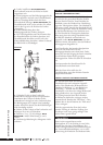
2. Fasten the pedal bands first into the retainer
at the device. Thread the band through the
pedal loop and push the band opening into the
projection in the pedal.
3. Fasten the pedal bands to the pedal outside.
Push the band through the locking buckle and the
band locks automatically.
4. The length of the band can be adjusted with the
locking buckle.