


22 STAR TRAC SPORT BIKES OWNER’S MANUAL
■ When your correct weight has been entered, press the key to accept the displayed value.
4. You are prompted to enter a time goal.
The default time is 99 minutes. You may enter any time from 1 to 99 minutes.
■ Use the
keys to enter your desired time goal; or press the or key, as necessary, to increase or
decrease the displayed value in 1 minute increments.
■ When your desired goal has been entered, press the key to accept the displayed value.
5. You are prompted to enter a resistance L
EVEL.
■ Use the keys to enter a resistance level (from 1 to 20) or press the or key, as desired, to increase or
decrease the resistance LEVEL in 1 unit increments.
■ When the desired resistance LEVEL has been entered, press the key to accept the displayed LEVEL.
6. If desired, you can use the personal fan during your workout (see “Using the Personal Fan” for details).
7. You can adjust the resistance L
EVEL during the program, using either of the following methods:
■ Use the keys to enter a resistance level (from 1 to 20). When the desired level has been entered, press the
key to confirm the resistance level.
■ Press the
or key, as desired, to increase or decrease the resistance LEVEL in 1 unit increments.
8. If you wish to pause the program, stop pedaling. The bike enters pause mode and a “P” flashes in the T
IME Window.
Resume pedaling within 25 seconds to continue your workout.
9. When you have reached your workout goal, the bike enters the Cooldown cycle (see “Cooldown Cycle” for details). If you
wish to exit the program before you have reached your workout goal, stop pedaling and allow the Pause timer to expire.
BURN CALORIES PROGRAM
The BURN CALORIES program provides an intense 3-peak ride that allows the user to pre-program a time goal, user weight and
maximum resistance level (from 1 to 20).
To operate the B
URN CALORIES program:
1. Mount the bike (refer to “Seat Adjustments” section) and begin pedaling,
■ If necessary, enter the Lockout ID to enable the bike for operation (see “Lockout ID Processing” for details).
2. Press the
key.
3. You are prompted to enter your weight. The bike displays a default weight of 155 pounds (70 kg). You may enter any
weight from 0 to 500 pounds (0 to 226 kg).
■ Use the
keys to enter your current weight; or press the or key, as necessary, to increase or decrease
the displayed weight in 1 pound (or 1 kg) increments.
■ When your correct weight has been entered, press the key to accept the displayed value.
4. You are prompted to enter a time goal.
The default time is 99 minutes. You may enter any time from 1 to 99 minutes.
■ Use the
keys to enter your desired time goal; or press the or key, as necessary, to increase or
decrease the displayed value in 1 minute increments.
■ When your desired goal has been entered, press the key to accept the displayed value.
5. You are prompted to enter a maximum resistance LEVEL.
■ Use the keys to enter a resistance level (from 1 to 20) or press the or key, as desired, to increase or
decrease the resistance LEVEL in 1 unit increments.
■ When the desired resistance LEVEL has been entered, press the key to accept the displayed LEVEL.
STAR TRAC SPORT BIKES OWNER’S MANUAL 15
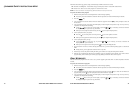
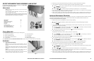
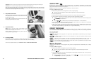
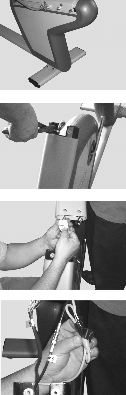
2. Install the Rear Foot
Lift up the rear of the bike frame and place the rear foot assembly
in position under the frame, aligning the holes in the foot with the
holes in the frame.
Using four M10 X 30 button head screws, secure the rear foot
assembly to the frame. Tighten all four screws securely.
3. Install the Display Console
NOTE: It is necessary to have one person support and position the
display console while a second person makes the cable connections.
Carefully pull the cable bundle out of the lower neck on the bike
frame. Use a pair of wire cutters or other suitable tool to cut and
remove the tie wrap from the cable bundle.
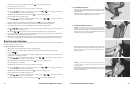
Hold the display console neck approximately one inch from the
neck brackets of the bike frame. Plug the display console power,
main I/O and Coax cable into their mating connectors in the
display console neck.
NOTE: The power connector is a “loose” fit. A strip of electrical tape
for securing the power connector is provided inside the lower neck
on the bike frame.
While holding the power cable connectors together, make a small
“bundle” of the cable, and wrap with electrical tape to prevent the
connectors from separating.
Step 2
Step 3a
Step 3c
Step 3b