


STAR TRAC TOTAL BODY TRAINER OWNER’S MANUAL 13
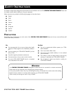
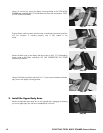
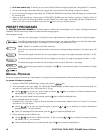
Using a 3/16” Allen wrench and five 1/4”-20 X 1/2” socket head screws, secure
the upper body arm to the hub.
Repeat for the left-side upper body arm.
NOTE: Be sure all five upper body arm mounting screws are tightened securely. Check
the condition of these screws regularly as described under “Preventative
Maintenance.”
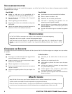
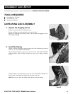
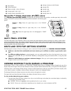
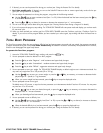
4. Leveling the Unit
Place the TOTAL BODY TRAINER on the floor in the position in which it will be used.
Use the leveling adjusters (located on the underside of the rear feet) to compensate
for uneven floor surfaces and to eliminate wobbling.
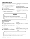
Operate the unit to check for proper operation.
Make sure that all screws are tight.
You have now completed assembly of your
STAR TRAC TOTAL BODY TRAINER
.
Step 4B
Step 5
OPERATING INSTRUCTIONS
Operating the
STAR TRAC TOTAL BODY TRAINER
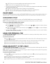
is very easy. Simply access the TOTAL BODY TRAINER by stepping on the Soft Trac
®
pedal, begin striding, and press QUICK START. Learning the features and incorporating the
STAR TRAC TOTAL BODY TRAINER
into your
members' fitness programs is just as easy. In this chapter, you will learn the display functions and how to get the most out of every
STAR
TRAC TOTAL BODY TRAINER
workout.
IMPORTANT: Before operating the TOTAL BODY TRAINER, you must be familiar with the following equipment limitations:
■ Maximum Weight: Your
STAR TRAC TOTAL BODY TRAINER
is designed for a maximum user weight of 350 lbs/159 kg. DO NOT
exceed the maximum user weight.
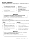
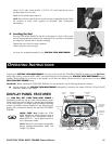
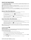
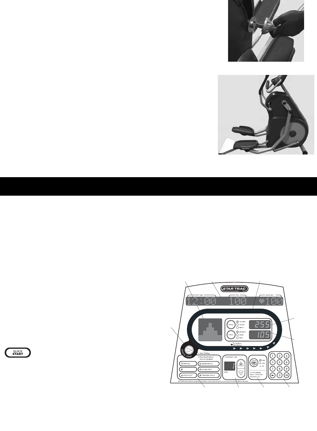
DISPLAY PANEL FEATURES
Your
STAR TRAC PRO /P-TBTX TOTAL BODY TRAINER
is
equipped to provide you and your users unlimited exercise oppor-
tunities. Experiment with its features to find the right combination
for your fitness regimen. The Display panel provides the operating
controls and display elements described in the following para-
graphs, and is consistent for both the Pro and P-tbtx TOTAL BODY
TRAINERs.
QUICK START Key: Enables the TOTAL
BODY TRAINER for manual operation using a
default weight as set in Maintenance Mode, a
default LEVEL of "1", and a default time limit as
set in Maintenance Mode.
NOTE: Default time and weight are adjustable
through Manager/Maintenance Mode. See
Chapter 7 for details.
PRESET
PROGRAM KEYS
QUICK START
KEY
LEVEL
ADJUST
NUMERIC
KEYPAD
UPPER DATA
INFORMATION
WINDOW
LOWER DATA
INFORMATION
WINDOW
MESSAGE
WINDOW
MOTIVATIONAL
TRACK
PROFILE
DISPLAY
FAN
CONTROL
TOTAL BODY