


STAR TRAC PRO BIKES O
WNER
’
S
G
UIDE
13
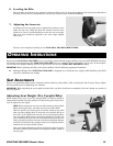
6. Leveling the Bike
Place the bike on the floor in the position in which it will be used. Use the leveling adjusters (located on the underside of
the front and rear feet) to compensate for uneven floor surfaces and to eliminate wobbling.
You have now completed assembly of your STAR TRAC PRO UPRIGHT BIKE.
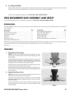
PRO RECUMBENT BIKE ASSEMBLY AND SETUP
Use the following procedures to unpack and assemble your STAR TRAC PRO RECUMBENT BIKE.
U
NPACKING
Open the shipping carton, remove all parts from the carton and foam inserts, and verify that the following parts are included in
your shipment:
Take time now to enter your Pro Bike serial number in the space below. If parts are missing, or if you have any operational ques-
tions, please call Star Trac’s Service Department at (800) 503-1221; have your serial number ready.
Serial No. ___________________________
A
SSEMBLY
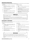
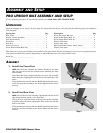
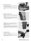
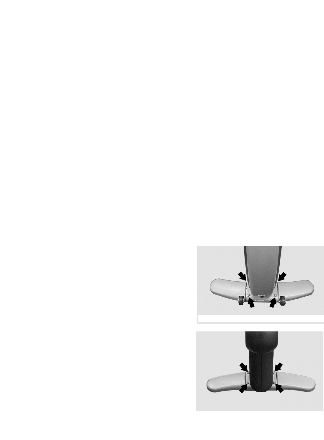
1. Install the Front Foot
NOTE: The front foot assembly has wheels attached to the front
edge. Be sure the wheels face forward when installing the front
foot assembly.
Stand the bike frame upright on the floor. Raise the front end of
the bike frame by placing a 2-inch Styrofoam spacer under the
front main beam. Insert four M10 X 30 button head screws
through the holes in the front foot attachment plate.
Position the front foot assembly under the attachment plate, align-
ing the holes in the foot with the four screws.
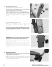
Using the 6mm hex wrench, secure the front foot assembly to the
frame with the four M10 X 30 button head screws.Tighten all four
screws securely.
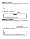
2. Install the Rear Foot
NOTE: Be sure the rear foot assembly is positioned with the curved
edge facing forward (similar to the front foot).
Lift up the rear of the bike frame and place the rear foot assembly
in position under the frame, aligning the holes in the foot with the
holes in the frame.
Using the 6mm hex wrench and four M10 X 30 button head
screws, secure the rear foot assembly to the frame. Tighten all four
screws securely.
Description Qty.
Bike Frame . . . . . . . . . . . . . . . . . . . . . . . . . . . . . . . . . . 1
Display Console Assembly . . . . . . . . . . . . . . . . . . . . . . . 1
Seat Frame Assembly . . . . . . . . . . . . . . . . . . . . . . . . . . 1
Front Foot . . . . . . . . . . . . . . . . . . . . . . . . . . . . . . . . . . . 1
Rear Foot . . . . . . . . . . . . . . . . . . . . . . . . . . . . . . . . . . . . 1
Pedals (set of two) . . . . . . . . . . . . . . . . . . . . . . . . . . . . . 1
Screw, Button Head, M10 X 30 . . . . . . . . . . . . . . . . . . . 8
Description Qty.
Screw, Socket Head, M10 X 10 . . . . . . . . . . . . . . . . . . . . 4
Screw, Flat Head, M6 X 20 . . . . . . . . . . . . . . . . . . . . . . . 4
Washer, Locking, M10 . . . . . . . . . . . . . . . . . . . . . . . . . . 4
Wrench, Hex, 6mm . . . . . . . . . . . . . . . . . . . . . . . . . . . . . 1
Wrench, Hex, 4mm . . . . . . . . . . . . . . . . . . . . . . . . . . . . . 1
Multi-end Wrench, 10mm, 12mm,15mm . . . . . . . . . . . . 1
Step 1
Step 2