


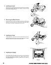
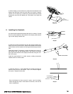
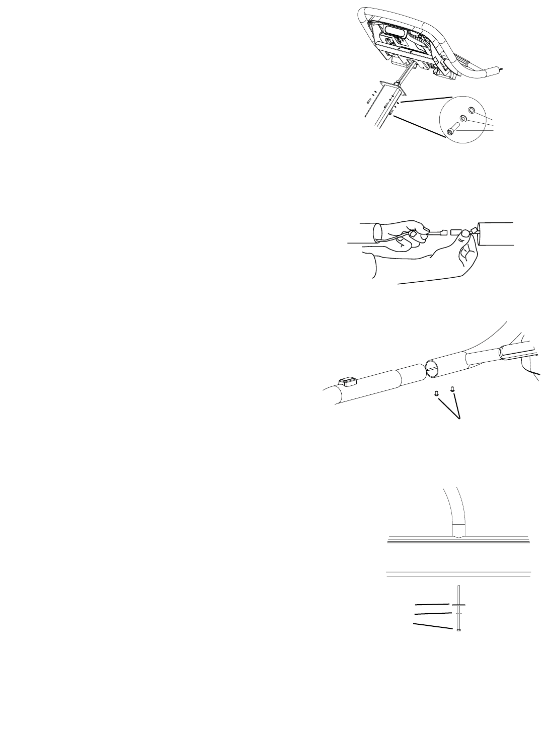
b) Lift the Display unit and take the (3) cables that are attached to the
display and feed them down the neck (this may require 2 people).
Use the 1/4” Hex allen key to install the (4) Socket Head Cap Screws
through the mount into the display unit. Be careful not to pinch the
cables.
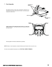
6. Installing the Handrails
a) Locate the left handrail (the handrail with the STOP switch). Connect
the STOP switch cable from the handrail to the display cable extend-
ing from the display handrail stub.
b) Insert the handrail connecting tube into the display handrail stub,
taking care not to pinch the S
TOP switch cable between the handrail
pieces. Make sure the handrail sits flush against the display handrail
stub.
Rotate the handrail, if necessary, to align the drilled hole in the dis-
play handrail stub with the threaded hole in the handrail connecting
tube. Secure the handrail to the display handrail stub using two 1/4”-
28 x 3/8” screws.
Install the right handrail in a similar manner, omitting instructions
related to the S
TOP switch cable.
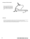
c) Insert the 5/16-18 x 7” Hex Head Bolt and washers through the
bottom of the frame into the handrail. Use a 1/2” wrench to tighten
the screws. Repeat for other side.
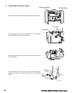
Once the display has been secured in place, route the display
cables through the cutout in the bottom of the neck, and into the
motor compartment.
STAR TRAC E SERIES TREADMILL OWNER’S MANUAL
13
Step 5b
Washer
Lock Washer
Socket Head Screw
1/4-28 x 3/8” Screws
Step 6a
Step 6b
Step 6c
2” OD Washer
5/16” Washer
5/16-18 x 7” Bolt