


ASSEMBLY INSTRUCTIONS
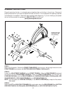
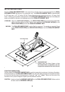
STEP 7
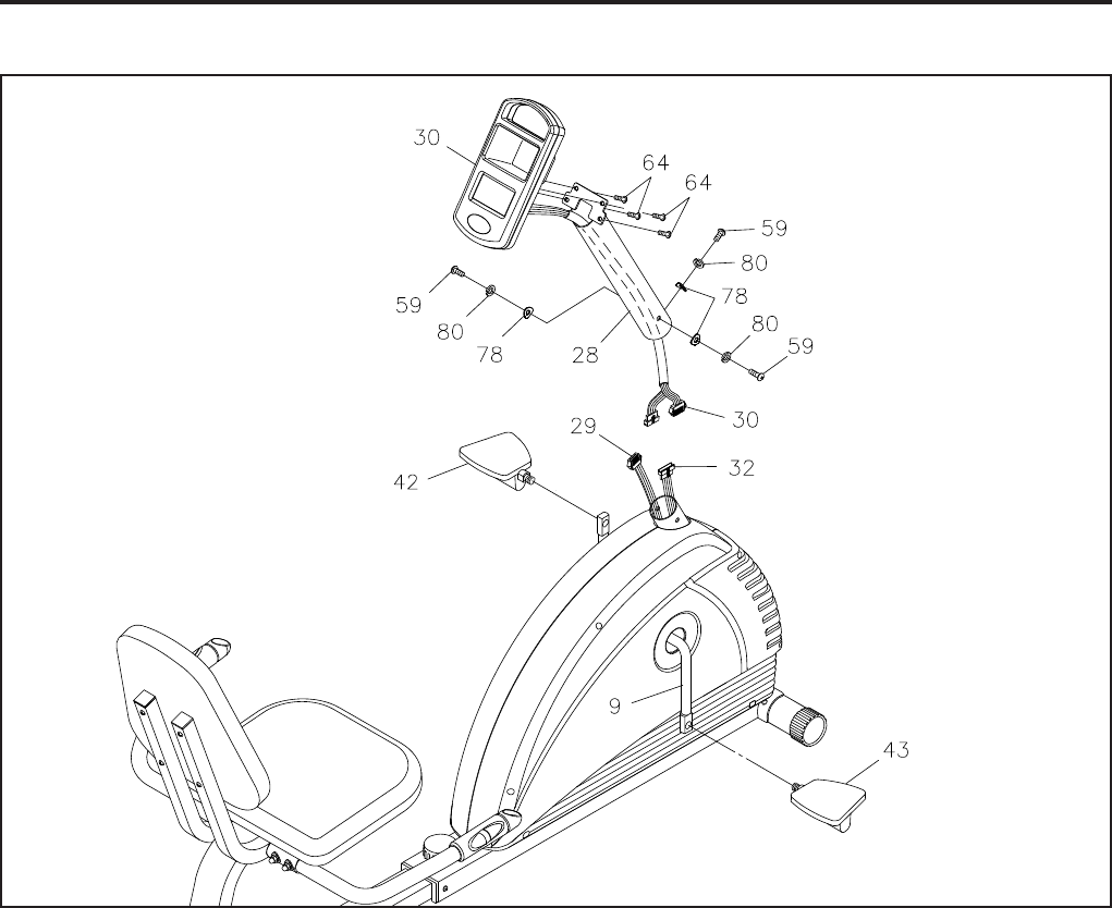
NOTE:
The RIGHT PEDAL(43) has R stamped on the end of the pedal shaft. The RIGHT PEDAL(43) has
right hand threads and is tightened by turning clockwise. The LEFT PEDAL(42) has L stamped on
the end of the pedal shaft. The LEFT PEDAL(42) has left hand threads and is tightened by turning
counter clockwise.
Thread the RIGHT PEDAL(43) onto the right side of the CRANK(9) as shown. Tighten the pedal securely.
Do the same to attach the LEFT PEDAL(42) onto the left side of the CRANK(9).
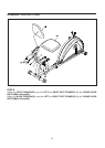
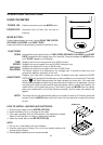
STEP 8
Install four AA batteries into the METER(30), four batteries included. See page 11 for detailed battery
installation instructions. Run the Extension Wire on the METER(30) through the METER POST(28). Attach
the METER(30) onto the METER POST(28) with ROUND HEAD SCREWS(M5x0.8x10mm)(64).
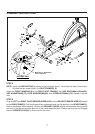
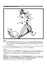
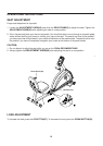
STEP 9
Plug the MOTOR CONTROL WIRE(29) and FRONT EXTENSION WIRE(32) to the Extension Wire on the
METER(30). Insert the METER POST(28) onto the FRONT FRAME(1) and secure with ROUND HEAD
BOLTS(M6x1x15mm)(59), LOCK WASHERS(M6)(80), and ARC WASHERS(M6)(78).
NOTE: Be careful not to damage the wires when attaching the METER(30).
9