


XE Series Elliptical
13
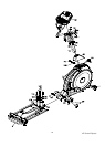
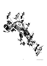
STEP 4: Plastic Parts Assembling
1. Match Connecting Arm Covers, (71-L) and (72-R), and install onto the Left and Right
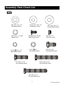
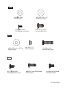
Connecting Arms (8&9) and secure with two M5x15mm Phillips Head Screws (82) and
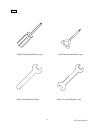
one 3.5x12mm Self Tapping Screw (107) by using Short Phillips Head Screw Driver
(125).
2. Install Sliding Wheel Covers (64) on each side and secure with four M5x15mm Phillips
Head Screws (82).
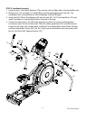
3. Install the two Stabilizer Covers (60) and (61) on the middle stabilizer bar with
M5x15mm Phillips Head Screws (82).
4. Install the Front Stabilizer Cover (59) on the front stabilizer with two M5x15mm Phillips
Head Screws (82).
5. Install the front (133) and rear (132) console mast covers with three M5 x 15m/m
Screws (82) and two 3.5x12m/m Self Tapping Screws (107).
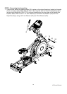
6. Install the two incline Cover brackets (156), with the hole for mounting the plastic cover
on the bent tab facing rearward, and secure them on the Incline Rail Assembly (2) with
four M6x10mm Phillips Head Screws (157). Install the Rear incline bar cover (73-2) on
the rail base with two M5 x 15m/m Screws (82).
7. Install the Rear Stabilizer Cover (73-3) on the Rear Stabilizer and the Cover brackets
(156) with four M5x15mm Phillips Head Screws.
8. This step to be performed after the elliptical power is plugged in. Run the incline to
position 8 and install the incline Rail front cover (73) up against the middle stabilizer
tube with two M5x15mm Phillips Head Screws.