


XE Series Elliptical
9
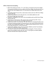
UNPACKING THE UNIT
1. Using a razor knife (Box Cutter) cut the outside, bottom, edge of box along the dotted Line. Lift Box
over the unit and unpack.
2. Carefully remove all parts from carton and inspect for any damage or missing parts. If damaged
parts are found, or parts are missing, contact your dealer immediately.
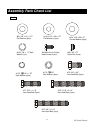
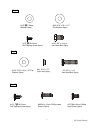
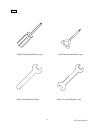
3. Locate the hardware package. The hardware is separated into four steps. Remove the tools first.
Remove the hardware for each step as needed to avoid confusion. The numbers in the instructions
that are in parenthesis (#) are the item number from the assembly drawing, for reference.
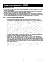
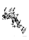
STEP 1: Incline Rail Assembly and Console Mast
1. Install the Incline Rail Assembly (2) into the U-channel bracket of the Main Frame (1).
Secure with the six bolts & associated hardware: install two 3/8x1-1/2 Hex Head bolts (77)
from the sides, with two 3/8x19mm Flat Washers (96) and two 3/8x7T Nylon Nuts (89).
From the top install; four 5/16x2-1/4 Hex Head bolts (167), four 5/16x20 Flat Washers
(100), four split washers (178) and four star washers (179), as shown in figure 1, and
tighten with the 13/14 mm Wrench (124).
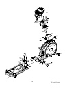
2. Connect the three Incline Motor Power lines by matching the; Red, White and Black color
codes of the wires and the 3-pin position sensor connector (Not shown in the drawing).
Locate the Console Mast (12) and Console Mast Cover (49) and slide the Cover onto
the Mast as far as it will go. Make sure the Console Mast Cover is facing the correct way.
At the top opening of the Main Frame of the elliptical are two Cables: the computer cable
(39) and Incline cable (36). Unravel and straighten out the two cables and feed them into
the bottom of the console mast tube and out of the top opening.
Install the Console
Mast (12) into the receiving bracket on the top of the Main Frame (1). Pull slightly on the
computer cables at the top of the mast while installing. This will ensure the cable does
not get pinched and shorted during console mast assembly.
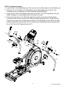
3.
Put one 3/8" x 2T Split Washer (128) onto the 3/8" x 2-1/4" Long Hex Head Bolt (75),
and the two 3/8
"
x 23 Curved Washers (104) onto the two 3/8" x 3/4" Short Hex Head
Bolts (76). Install, and hand tighten, the Long Hex Head Bolt through the left side of the
receiving bracket into the Console Mast. Using the 13/14m/m Wrench tighten the three
bolts and the fourth bolt, which is pre-installed, firmly. These bolts should be tightened as
much as you possibly can
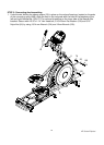
4. Plug all of the connectors into the back of the console (Computer Cable (39), Incline Cable
(36), two Hand pulse Cables (44), Resistance switch wire (146) and Incline switch wire
(146-1)). Secure the Console (32) on the console mounting plate with four M5x10m/m
Phillips Head Screws (85).
Assembly Instructions XE400