


8
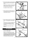
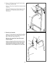
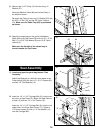
13. Press Arm Assembly—Locate and open the parts
bag labeled “ARM ASSEMBLY.”
Press a 1” x 7/8” Plastic Bushing (75) onto each
welded spacer on the Press Frame (17). Align the
welded spacers on the Press Frame with the tube (A)
on the Top Frame (55). Note: This will be a tight fit.
The Plastic Bushings should fit onto the ends of
the tube on the Top Frame. Lubricate the 3/8” x 7 1/2”
Bolt (59). Attach the Press Frame to the Top Frame
with the Bolt and a 3/8” Nylon Jam Nut (83).
13
Arm Assembly
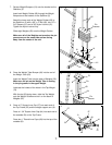
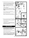
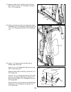
12. Press a 2” Square Inner Cap (27) into the Press Seat
Frame (77). Slide the Press Seat Frame onto the
5/16” x 2 1/2” Carriage Bolts (1) in the Press Base
(51).
Insert two 5/16” x 2 3/4” Bolts (11) through the brack-
et on the Seat Frame and through the holes in the
Press Upright (42). Hand tighten a 5/16” Nylon
Locknut (3) and a 5/16” Flat Washer (8) onto each
Carriage Bolt.
Tighten all Nylon Locknuts used in steps 4
through 12.
12
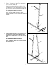
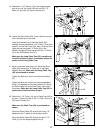
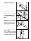
11. Attach the upper ends of the Weight Guides (62) to
the Top Frame (55) with a 3/8” x 6” Bolt (60), two 1/2”
x 3/4” Spacers (61) and a 3/8” Nylon Locknut (21).
Tighten the Nylon Locknut fully.
11
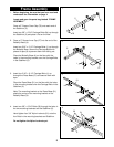
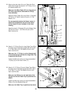
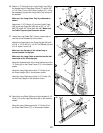
10. Place the Top Frame (55) on top of the two Uprights
(56) and (42) in the direction shown. Align the holes in
the Top Frame with the holes in the brackets on the
Uprights.
Insert four 5/16” x 2 3/4” Bolts (11) with four 5/16” Flat
Washers (8) through the holes in the Top Frame (55)
and the brackets on the Uprights. Hand tighten a
5/16” Nylon Locknut (3) unto each Bolt.
Do not tighten the Nylon Locknuts yet.
10
11
8
8
3
3
55
61
60
21
62
1
11
8
77
42
27
3
3
59 Lubricate
83
17
75
42
56
55
55
A
51
3