


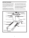
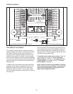
8
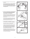
7. Place the treadmill in the storage position (see HOW TO
FOLD AND MOVE THE TREADMILL on page 20).
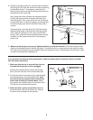
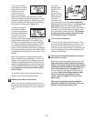
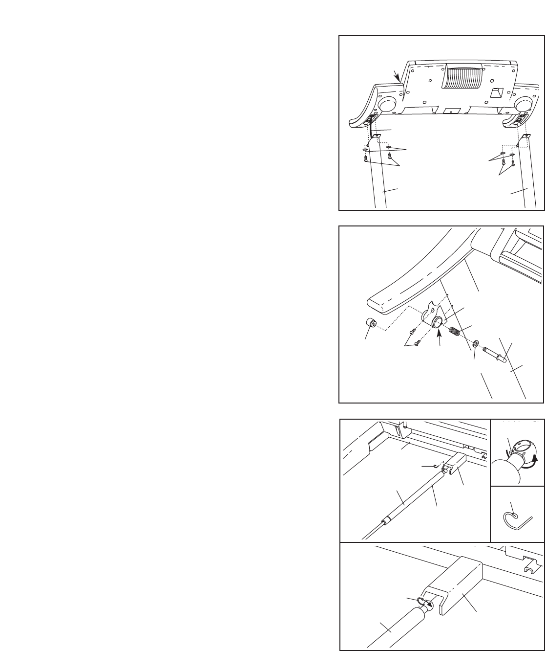
Next, place the cylinder end of the Gas Spring (92) near
the bracket on the base of the Uprights (84).
See the two small inset drawings. Using your fingernail
or the end of a screwdriver, press on the end of the
Spring Pin (25) to loosen it from the Gas Spring (92).
Next, rotate the Spring Pin and pull it out of the Gas
Spring.
Be careful to avoid losing the Spring Pin.
Note: Extra Spring Pins are included.
See drawing 7a. Press the cylinder end of the Gas
Spring (92) onto the ball on the bracket. Next, insert the
end of the Spring Pin (25) into two of the small holes in
the end of the Gas Spring. Then, rotate the Spring Pin
until it clips onto the Gas Spring.
92
25
92
25
7
7a
84
Bracket
Cylinder
Bracket
25
25
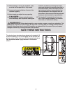
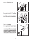
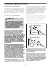
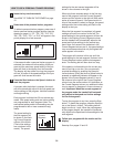
6. Attach the Latch Housing (73) to the left Upright (84) with
two Screws (3);
start both Screws and then tighten
them. Note: Make sure that the large hole in the
Latch Housing is on the indicated side.
Remove the knob from the pin. Make sure that the collar
and the spring are on the pin. (Note: If there are two col-
lars, place one on each side of the spring.) Next, insert
the pin into the Latch Housing (73). Then, tighten the
knob onto the pin.
Plug in the power cord as described on page 10, and
turn on the power as described on page 12. Note: The
treadmill may automatically rise to the maximum incline
level and then return to the minimum level.
Pin
Large
Hole
Knob
3
6
5
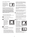
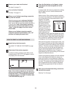
. Insert the Wire Harnesses (77, 78) down into the right
Upright (84).
Set the console assembly on the Uprights (84).
Be care-
ful to avoid pinching the Wire Harnesses (77, 78).
While a second person holds the console assembly, at-
t
ach it with four Console Bolts (64) and four Star Washers
(8) as shown; start all four Console Bolts and then
firmly tighten them.
Console
Assembly
64
77, 78
64
8
8
84
84
5
84
73
Spring
Collar