


7
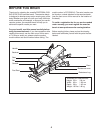
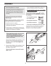
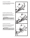
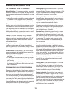
6. Orient the Backrest (12) so that the narrow end is
over the top of the Backrest Frame (11). Attach
t
he Backrest to the Backrest Frame with two M6 x
25mm Screws (77) and two M6 x 45mm Screws
(
78).
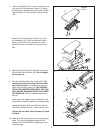
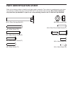
8. Attach the Foot Plate (9) to the Rail (4) with four
M6 x 25mm Button Screws (57). Do not tighten
the Screws yet.
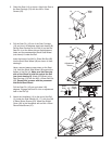
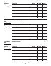
7. Slide the top of the Backrest Frame (11) under
the Handlebar (10). Pivot the Backrest Frame
down onto the Rail (4) so that the pin on the
Backrest Frame is inserted into the hole in the
Rail.
7
8
9
6
1
2
11
77
78
11
Hole
Narrow
End
4
10
9
57
57
57
4
76
76
4
76
63
84
9
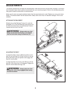
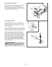
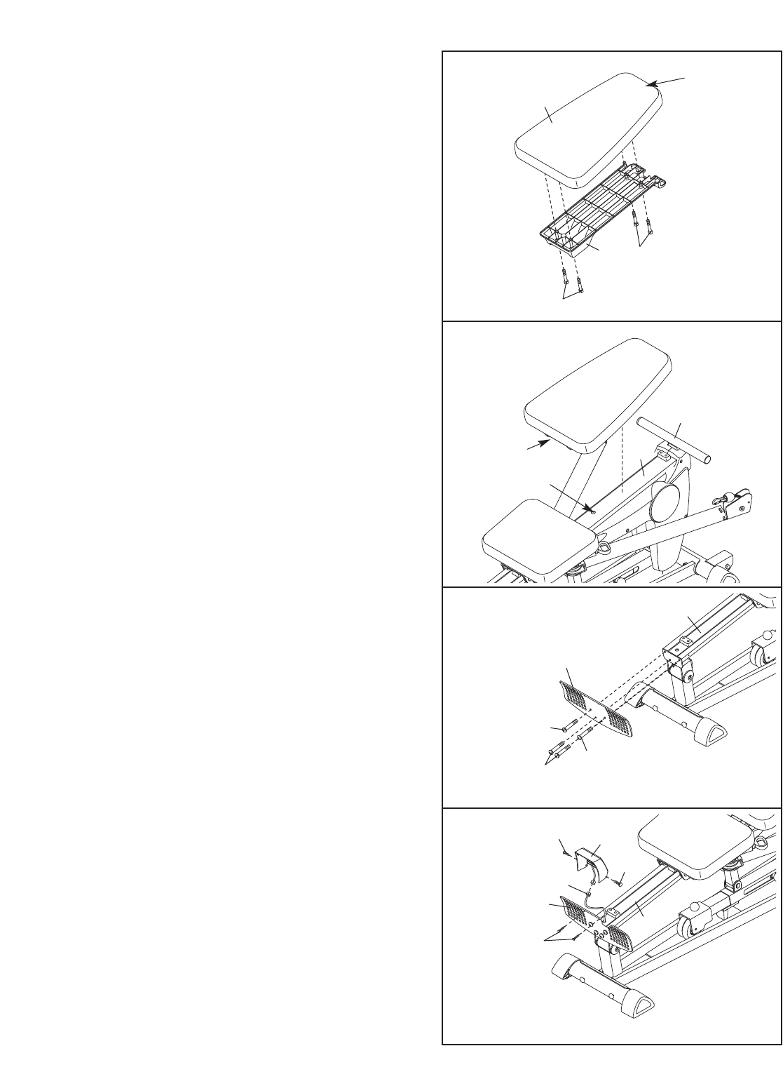
9. Connect the Wire (63) to the Console (84). The
connector should slide easily into the socket
and snap into place. If it does not, turn the con-
nector over and then insert it. IF THE CONNEC-
TOR IS NOT INSERTED PROPERLY, THE CON-
SOLE MAY
BE DAMAGED WHEN THE POWER
IS TURNED ON.
Push the excess Wire into the
Rail (4).
Insert three “AA” batteries (not included) into the
Console (84). Alkaline batteries are recommended.
Attach the Console (84) to the Rail (4) and the
Foot Plate (9) with four M4 x 16mm Screws (76).
Tighten the four M6 x 25mm Screws (57) used
in step 8.
10. Make sure that all parts have been properly tight-
ened. The use of the remaining parts will be
explained in ADJUSTMENTS, beginning on the
following page.