


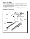
7
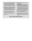
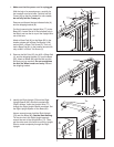
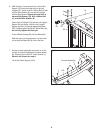
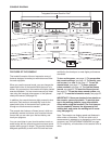
2. Remove the M10 Nut (33), the M10 x 50mm Bolt
(4), and the shipping bracket (C) from the Base
(85). Attach a Wheel (86) with the Bolt and the
Nut that you just removed. Do not overtighten
the Nut; the Wheel must turn freely. Discard
the shipping bracket.
85
4
33
C
2
86
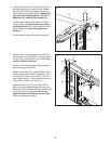
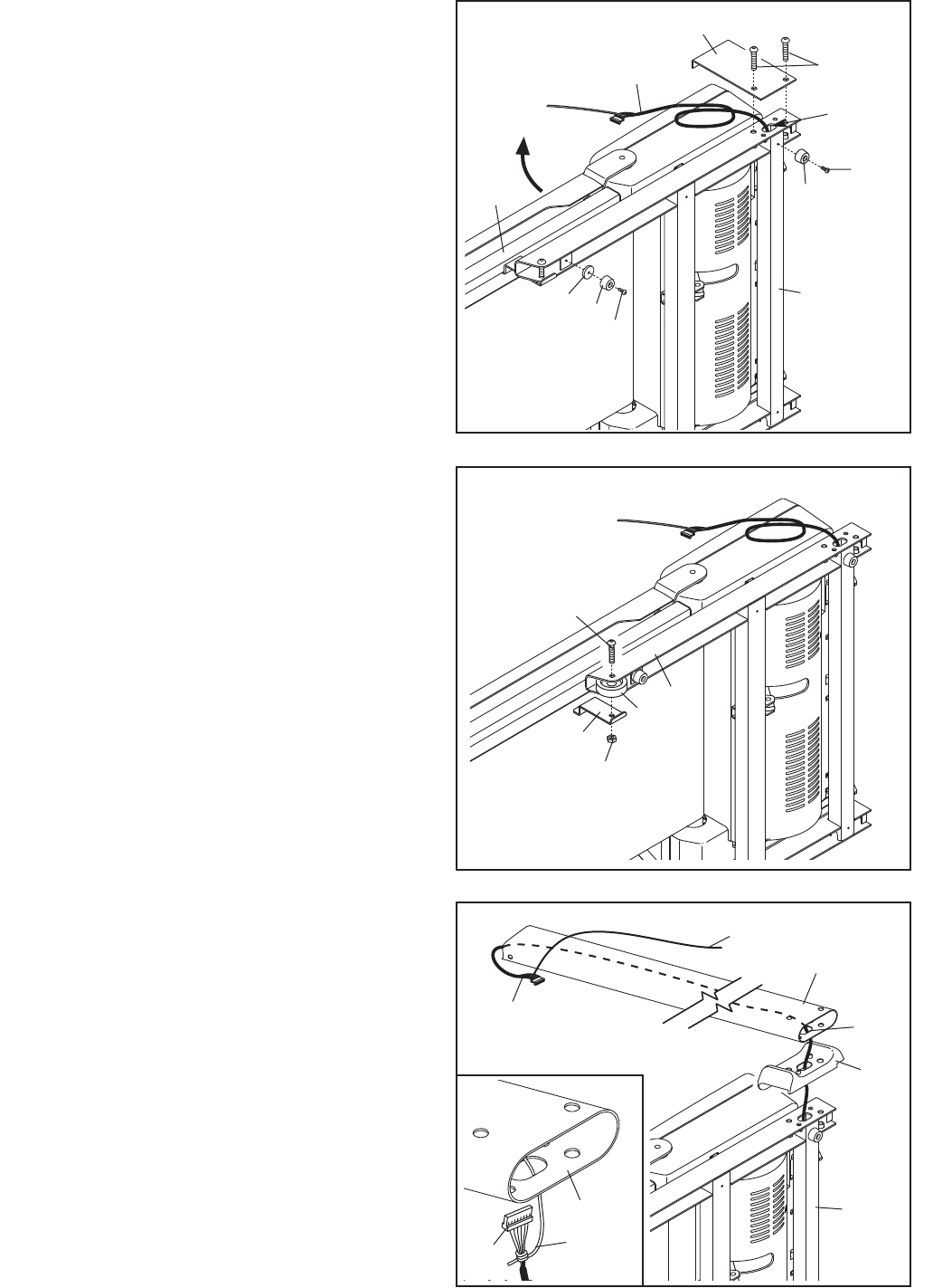
1
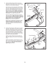
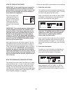
. Make sure that the power cord is unplugged.
With the help of a second person, carefully tip
the treadmill onto its left side. Partially fold the
F
rame (48) so that the treadmill is more stable;
do not fully fold the Frame yet.
Remove and discard the two indicated bolts (A)
a
nd the shipping bracket (B).
Cut the tie securing the Upright Wire (77) to the
Base (85). Locate the tie in the indicated hole in
the Base, and use the tie to pull the Upright Wire
out of the hole.
Attach a Base Pad (81) to the Base (85) in the
location shown with a Base Pad Spacer (104)
and an M4.2 x 25mm Tek Screw (2). Then, at-
tach a Base Pad (81) in the location shown with
only an M4.2 x 25mm Tek Screw (2).
85
2
48
81
1
81
2
77
Hole
104
B
A
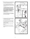
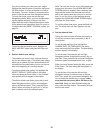
3. Identify the Right Upright (78) and the Right
Upright Spacer (80), which are marked with
“Right” stickers. Insert the Upright Wire (77)
through the Right Upright Spacer as shown. Set
the Right Upright Spacer on the Base (85).
Have a second person hold the Right Upright
(78) near the Base (85). See the inset drawing.
Tie the wire tie in the Right Upright securely
around the end of the Upright Wire (77). Then,
pull the other end of the wire tie until the Upright
Wire is routed completely through the Right
Upright.
85
77
78
80
77
3
Wire
Tie
78
77
Tie