


10
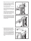
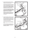
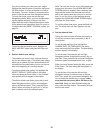
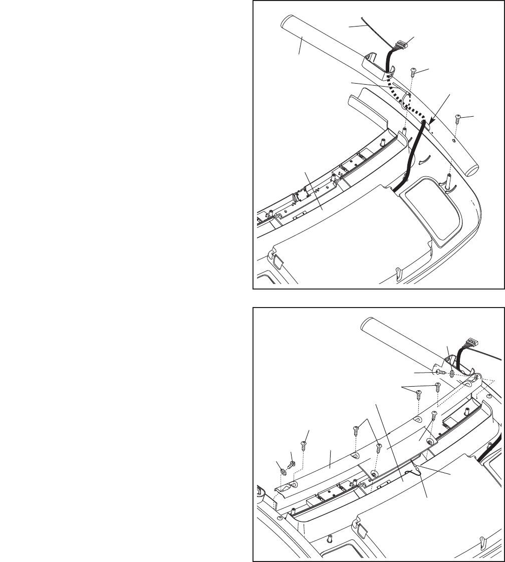
8. Identify the Right Handrail (90), which has a
large hole in the location shown. Hold the Right
Handrail near the console assembly.
Insert the tie on the console wire into the large
h
ole in the Right Handrail (90) and out of the top
as shown; use needlenose pliers if necessary.
Next, insert the included plastic tie through the
Right Handrail as shown. Make sure that the
plastic tie holds the console wire against the
inner side. Then, tighten the plastic tie.
Attach the Right Handrail (90) with two M4.2 x
19mm Screws (1). Make sure that no wires are
pinched. Start both Screws before tightening
either of them; do not overtighten the
Screws. Then, remove the plastic tie.
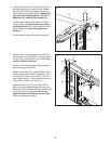
Attach the Left Handrail (not shown) to the
console assembly in the same way. Note:
There are no wires on the left side of the con-
sole assembly.
90
Tie
8
1
1
Large Hole
Console
Wire
Plastic Tie
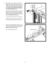
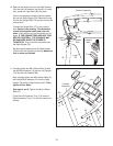
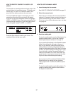
9. Hold the Pulse Support (109) near the console
assembly. Connect the Console Ground Wire
(40) on the Pulse Support to the ground wire on
the console assembly. Then, insert the ground
wires into the console assembly and set the
Pulse Support on the console assembly. Make
sure that no wires are pinched.
Tighten two M4 x 20mm Screws (3) with two
M4.2 Star Washers (70) into the Pulse Support
(109).
Tighten the six M4.2 x 19mm Screws (1) from
step 7 into the Pulse Support (109) and the con-
sole assembly. Start all six Screws before
tightening any of them.
3
70
Ground
Wire
1
1
70
1
1
9
109
40
3
Console
Assembly
Console Assembly