


358
53.
54.
60.
EX350 ASSEMBLY INSTRUCTIONS
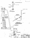
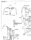
SECURELY assemble the BACK PAD to MAIN UPRIGHT using two (2) 3/8 X 3 IN. FlEX HEAD
BOLTS and two (2) 3:8 IN. LOCK WASHERS. (HIDEM WELT CLIP SHOULD BE FACING
DOWN)
¯
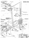
To assemble the PEC DEC LOOP CABLE, start by LOOSELY attaching each end of the CABLE to
CAMS of the LEFT and RIGHT PEC DEC ARMS, using two (2) 5116 X I IN. HEX HEAD
BOLTS.four (4) 5 "16 IN. WASHERS. two (2) 5/16 IN. LOCK WASHERS. and two I’.2) 5/16
NUTS. (SEE DETAIL C)
¯
Rut1 CABLE back to the PULLEYS on the PULLEY BRACKET SUPPORT. Drape the CABLE
over the PULLEYS o,a both sides. Position the CABLE RETAINING CLIPS over the top of the
CABLE at a -15 degree angle. This will create a LOOP in the center of the hanging CABLE. (SEE
DETAIL A)
¯ LOOSELY assemble one (I) 4-I/2 DIA PULLEY with I IN. BUSHING to the CENTER PULLEY
BRACKET a~ shown ~n (DETAIL D). using one (I) 3!8 X 2 IN. HEX HEAD BOL’I;
CABLE RETAINING "L" CLIP, and one (I) .~/8 IN. LOCKNUT.
¯ Assemble the CENTER PULLEY BRACKET ASSEMBLY over the LOOP CABLE as Sh.o~vn on
drawing. Position the CABLE RETAINING CLIP under the CABLE. (SEE DETAIL A)
Tiahten all LOOSE PULLEY and CABLE connecttons.
Attach the end ofone { i ~ 21 LINK CHAIN to the CENTER PULLEY BRACKET using one (1) 5/16 IN.
SNAP LINK. (SEE DETAIL B)
Attach the other end of the CHAIN to the end of the CABLE in the LOW ROW SWIVEL BRACKET on
"the MAIN .UNIT using one (I) QUICK LINK.
TIGHTEN ALL BOLT CONNECTIONS AT THIS ThME. (NOTE: IF PRESS ARM APPEARS TO
BE OFF CENTER.ALIGN PULLEYS WITH STOP ON .BACK SEAT SUPPORT BEFORE AND
DURING TIGHTENING)
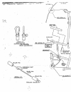
*** REFER TO ASSEMBLY DRAWING #3 FOR STEPS 59 THRU 67 ***
¯
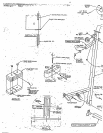
Attach LAT BAR to PRIMARY CABLE with one (1) 5:16 IN. SNAP LINK (SEE DETAIL
¯ Attach one I I ) "; 16 IN. SNAP LINK toeach end of the second 21 LINK CHAIN to l~e used with
eitherthe LOW ROW PULLEY on the LEG CURL ARM ASSEMBLY or the UPPER PULLEY.
¯
NOTE: SEE TH E EXERCISE WALL CHART FOR INEORMATION ON THE VARIOUS
ACCESSORi ES THAT ATTACH TO THE 5/16 IN. SNAP LINKS.
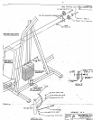
AttaCh eight (8~ PARAGLIDE STP, IPS to the SEAT SUPPORT TUBE on the BACK SEAT SUPPORT.
as sho~ n in (DETA I L H) using the tbllowing steps:
,
Tlaoroughl.~ cle;m all inside surfaces ~here the PARA~LID~- strip~ are to be attached.
Remox e the paper backin’.2-’ from the PARAGLIDE stt~ips and firmly apply the
m
to all shown surfaces
( 8 places ~.
10