


FIGURE
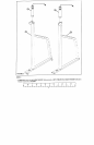
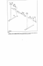
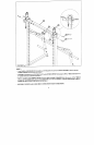
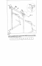
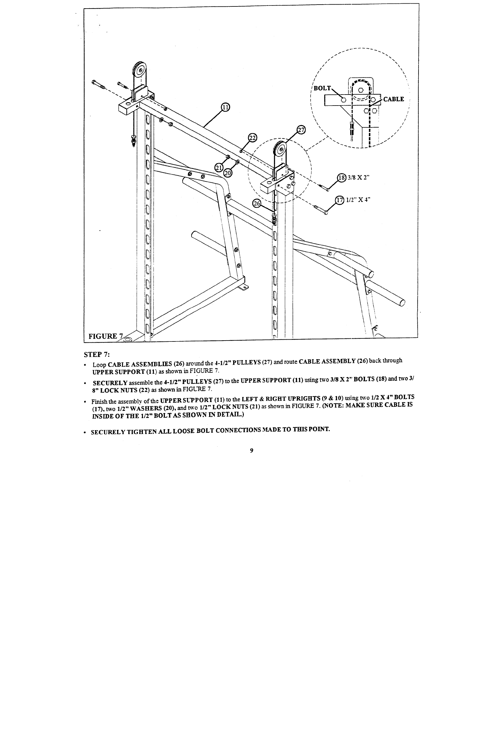
STEP 7:
¯ Loop C.~BLE ASSEMBLIES (26) around the 4-1/2" PULLEYS (27) and route CABLE ASSENEBLY (26) back through
UPPER SUPPORT (11)as shown in FIGURE 7.
¯
SECURELY assemble the 4-1/2" PUI_LEYS (27) to the UPPER SUPPORT (11) using t~’o 3/8 X 2" BOLTS (18) and
8" LOCK NUTS (22) as: shown in FIGURE
¯
Finish the assembly of the UPPER SUPPORT (11) to the LEFT & RIGHT UPRIGHTS (9 & 10) using Bvo 1/2 X 4" BOLTS
(17), two 112" W~SHEILS (20), and two 1/2" LOCK NUTS (21) as shown in FIGURE 7. (NOTE: MAKE SURE C.~BLE
INSIDE OF THE 112" BOLT AS SHOVI,’,’N L-N DETAIL.)
¯
SECURELY TIGHTEN ALL LOOSE BOLT CONNECTIONS MADE TO THIS POINT.
9