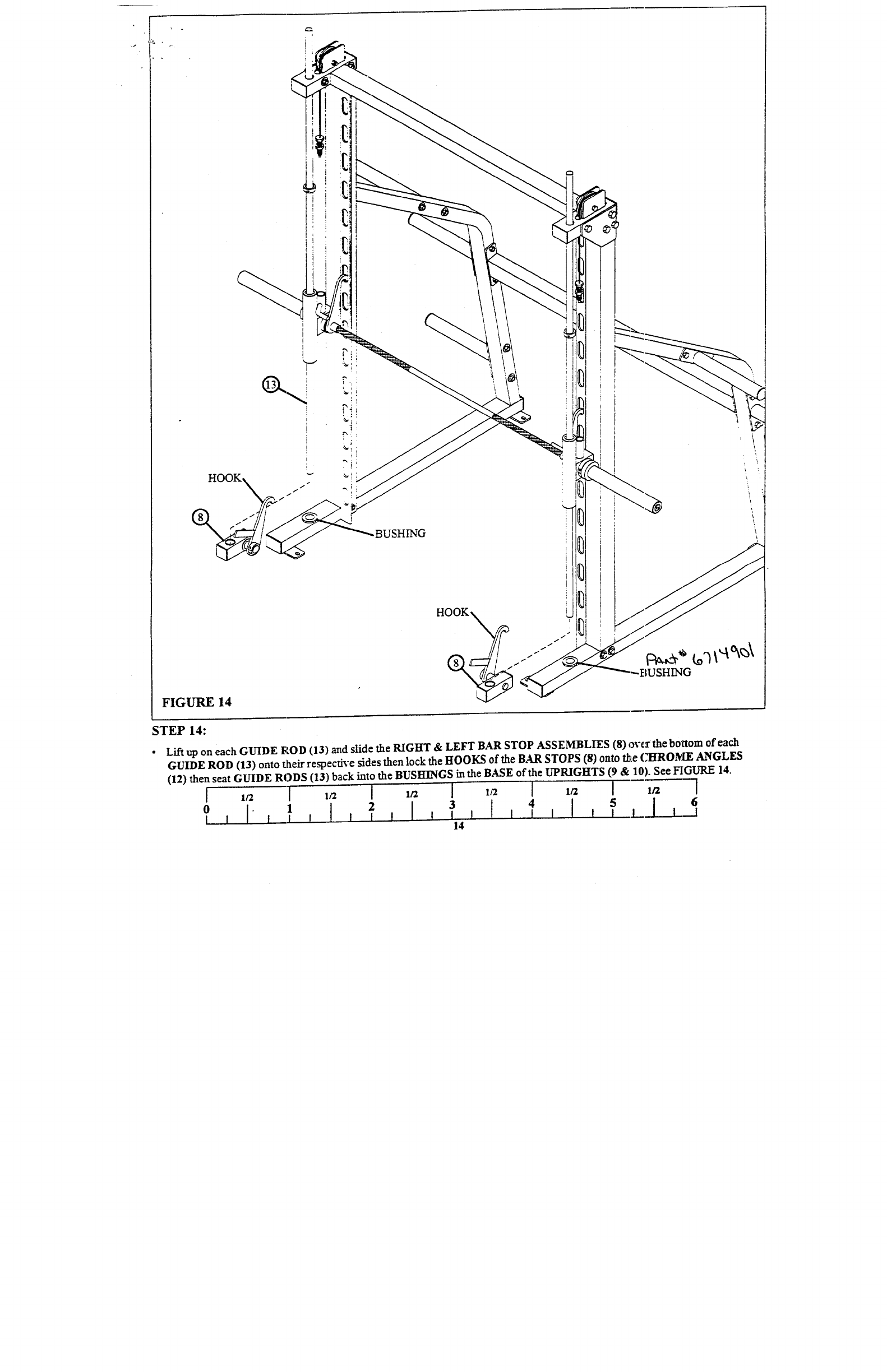
FIGURE 14
BUSHING
HOOK I~
~USHI NG
STEP 14:
¯ Lift up on each GUIDE ROD (13) aad slide the RIGHT & LEFT BAR STOP ASSEMBLIES (8) ove~’the bottom of
GUIDE ROD (13) onto their respecfi~e sides then lock the HOOKS of the BAR STOPS (8) onto t~e CHROME A~GLES
(12) then seat GUIDE RODS (13) back into the BUSHINGS inthe BASE of the UPRIGHTS (9 10). Se e FIGURE 14
6
4 I l ~ I--
0 - 1 I l l l


