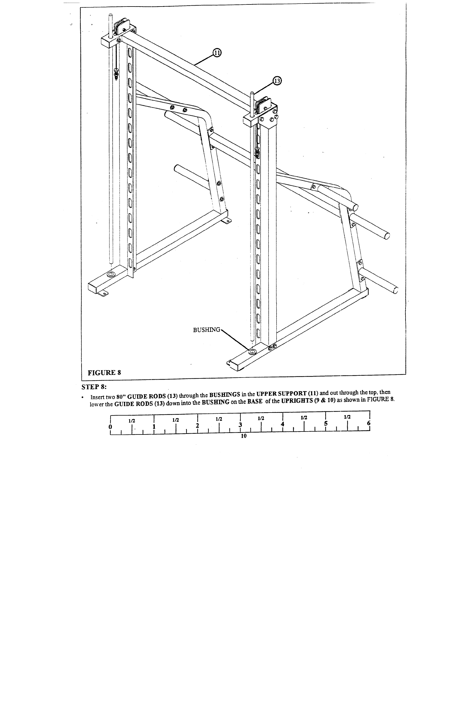
FIGURE 8
STEP 8:
¯
Insert va, o 80" GUIDE ftODS (13) through the BUSHENGS in the UPPER SUPPORT (11) and out lhrough the top,
lower the GUIDE RODS (13) dovm into the BUSHING onthe BASE of the UPRIGHTS (9 & 10) a~; shown in FIGURE
5 I I
1
4
[ I I J-
0 [ ! I I
I I ~0


