


I
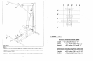
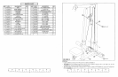
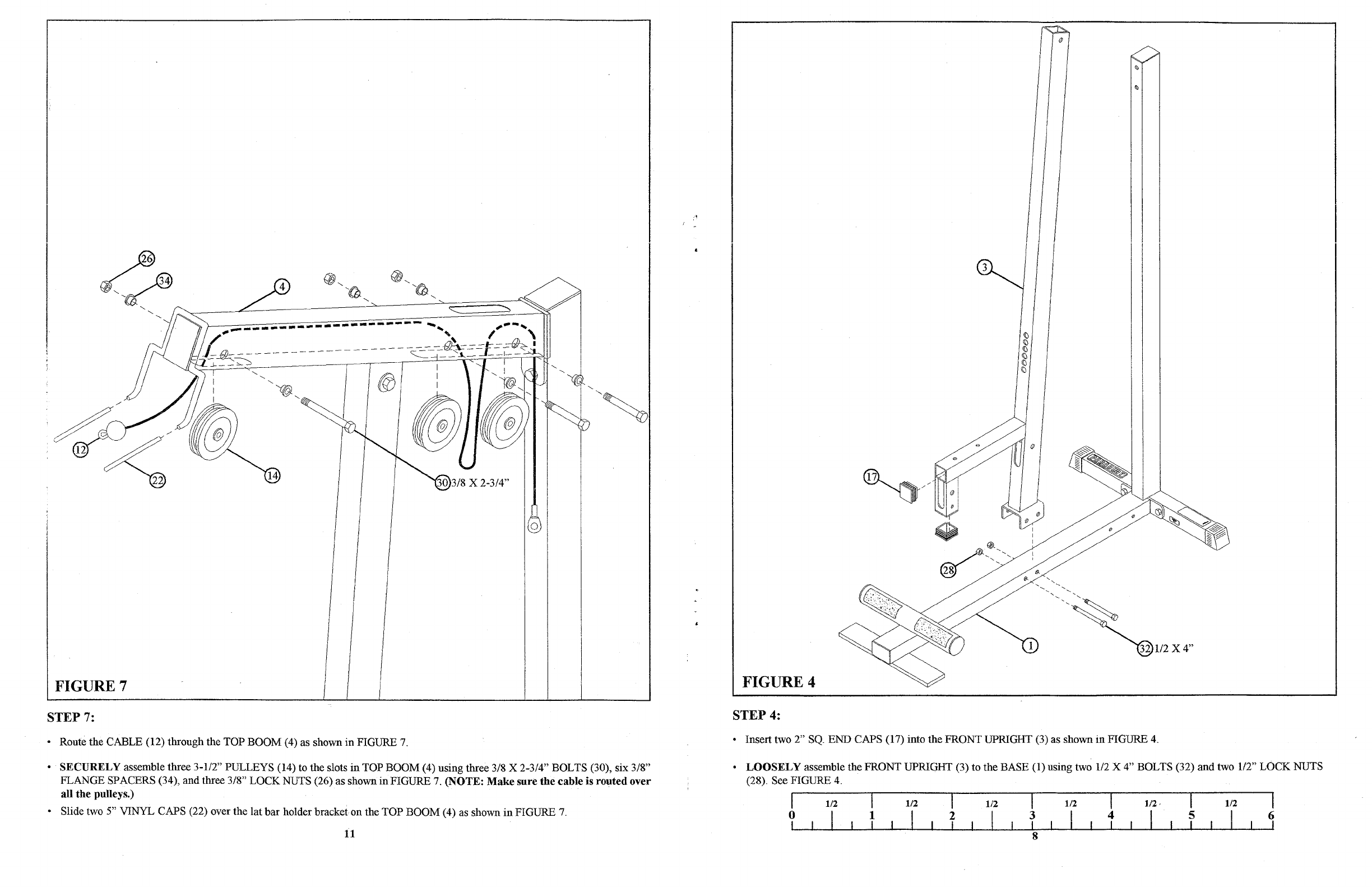
FIGURE 7
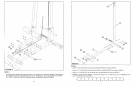
FIGURE 4
STEP 7:
STEP 4:
• Insert two 2"
SQ.
END CAPS (17) into the FRONT UPRIGHT (3) as shown
in
FIGURE
4.
•
LOOSELY
assemble the FRONT UPRIGHT (3) to the BASE (1) using two
112
X 4" BOLTS (32) and two
112"
LOCK NUTS
(28). See FIGURE
4.
• Route the CABLE (12) through the TOP BOOM (4) as shown
in
FIGURE
7.
•
SECURELY
assemble three 3-112" PULLEYS (14) to the slots
in
TOP BOOM (4) using three 3/8 X 2-3/4" BOLTS (30), six 3/8"
FLANGE SPACERS (34), and three 3/8" LOCK NUTS (26) as shown
in
FIGURE 7.
(NOTE:
Make
sure
the
cable is
routed
over
all
the
pulleys.)
• Slide two 5" VINYL CAPS (22) over the lat bar holder bracketon the TOP BOOM (4) as shown
in
FIGURE
7.
11
I
o
I
1/2
I
I
1
I
1/2
I
I
2
I
1/2
I
I
3
I
8
1/2
I
I
4
I
I
5
I
1/2
I
I
6
I