


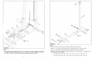
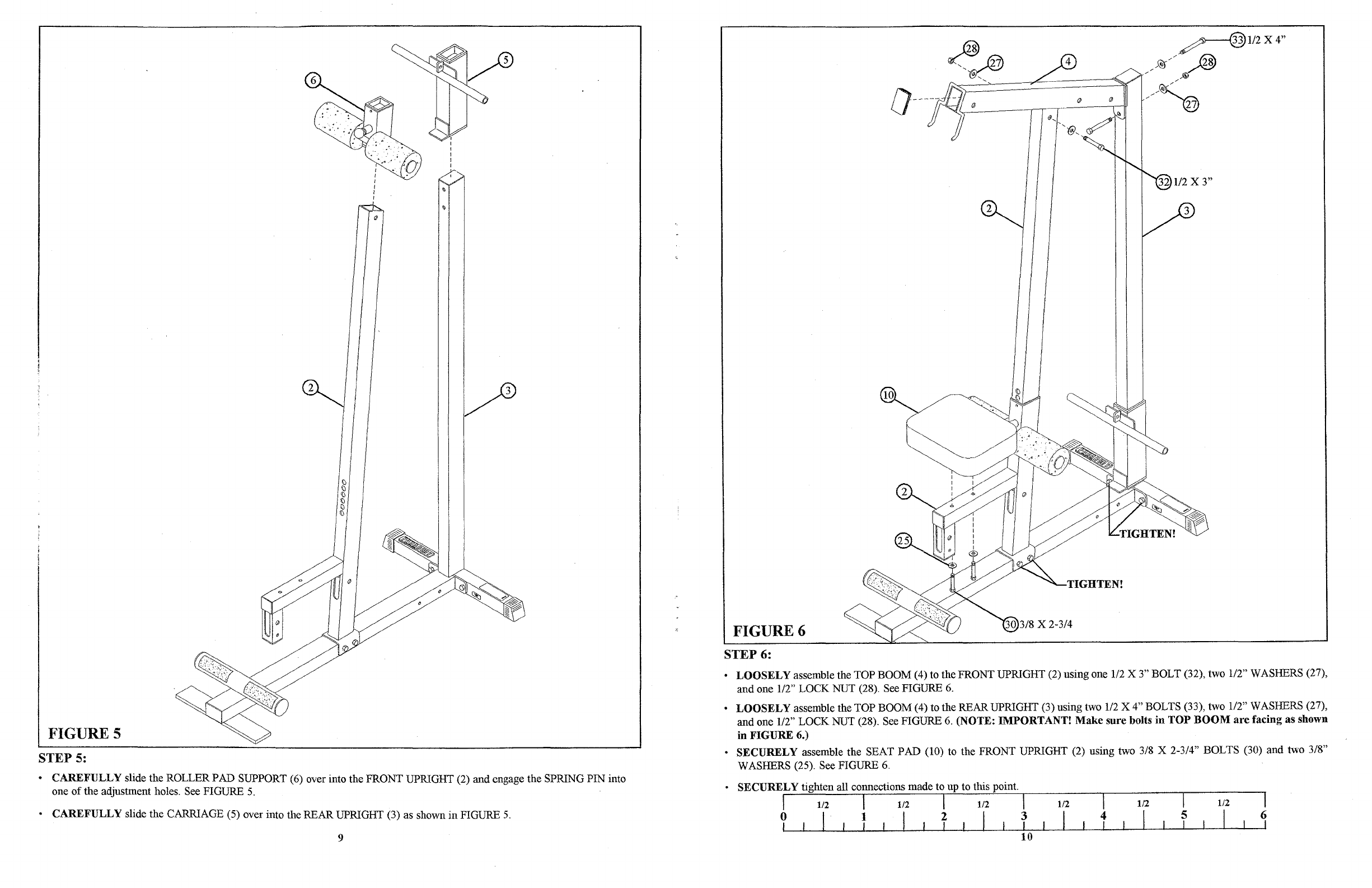
FIGURE 5
STEP
5:
•
CAREFULLY
slide the ROLLER PAD SUPPORT (6) over into the FRONT UPRIGHT (2) and engage the SPRING PIN into
one
of
the adjustment holes. See FIGURE
5.
o
CAREFULLY
slide the CARRIAGE (5) over into the REAR UPRIGHT (3) as shown in FIGURE
5.
9
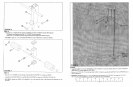
FIGURE 6
STEP 6:
o
LOOSELY
assemble the TOP BOOM (4) to the FRONT UPRIGHT (2) using one
112
X 3" BOLT (32), two 1/2" WASHERS (27),
and one
112"
LOCK NUT (28). See FIGURE
6.
o
LOOSELY
assemble the TOP BOOM (4) to the REAR UPRIGHT (3) using two
112
X 4" BOLTS (33), two 1/2" WASHERS (27),
and
one
112"
LOCK NUT (28). See FIGURE
6.
(NOTE:
IMPORTANT!
Make
sure
bolts
in
TOP
BOOM
are
facing
as
shown
in
FIGURE
6.)
o
SECURELY
assemble the SEAT PAD (10) to the FRONT UPRIGHT (2) using two 3/8 X
2-314"
BOLTS (30) and two 3/8"
WASHERS (25). See FIGURE
6.
o
SECURELY
tighten all connections made to up to this point.
I 1/2 I 1/2 I 1/2 I 1/2 I 1/2 I 1/2 I
? I
fiT
I
fit
I T
1--L---1~
-...1.-----1-
1
O-::--L---l----J.-~--I-----J'----l------I--J--