


7
FI
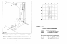
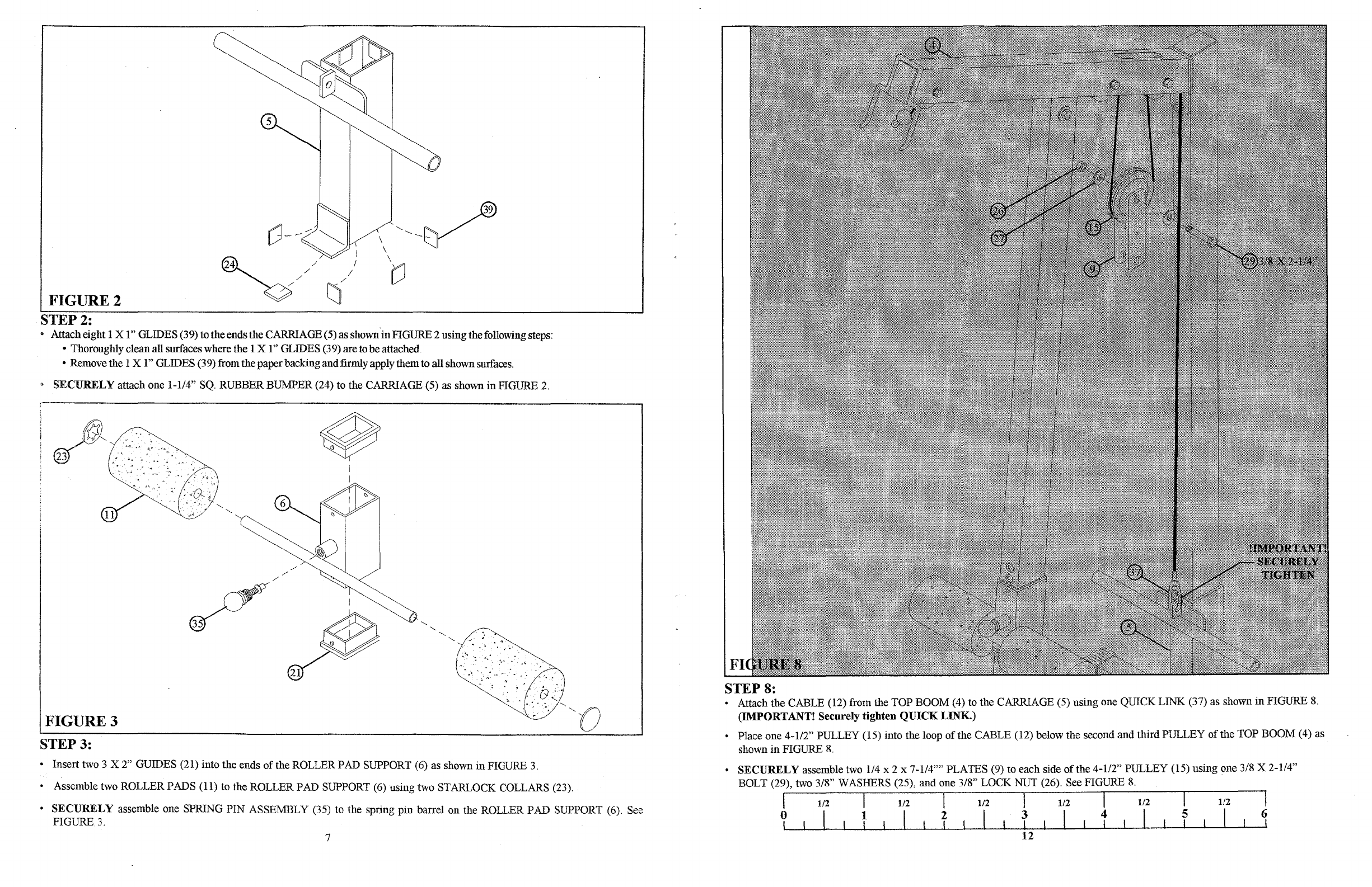
STEP 8:
Attach the CABLE (12) from the TOP BOOM (4) to the CARRIAGE (5) using one QUICK LINK (37) as shown
in
FIGURE
8.
(IMPORTANT! Securely tighten
QUICK
LINK.)
• Place one 4-112" PULLEY (15) into the loop
of
the CABLE (12) below the second and third PULLEY
of
the TOP BOOM (4) as
shown
in
FIGURE
8.
SECURELY
assemble two 1/4 x 2 x 7-114'''' PLATES (9) to each side
of
the 4-1/2" PULLEY (15) using one 3/8 X 2-1/4"
BOLT (29), two 3/8" WASHERS (25), and one 3/8" LOCK NUT (26). See FIGURE
8.
I 1/2 I 1/2 I 1/2 I 1/2
1--t-/2----,Ir---
t
-/
2
--1
?L--l-...l-I--L---!tL-i--L1
-L--IT---l...--LI
--l.--!f~--LI
--L-~1--L--l-1
--l-----LT--I-_I'----'----'~
12
o
"
..
"
..
".
:.
.....
6~_
........
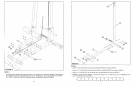
FIGURE
3
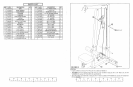
FIGURE 2
9
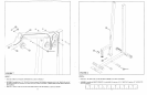
SECURELY
attach one 1-1/4"
SQ.
RUBBER BUMPER (24) to the CARRIAGE (5) as shown in FIGURE
2.
STEP
2:
• Attach eight 1
Xl"
GLIDES (39) totheends the CARRIAGE (5) as shown
in
FIGURE 2 usingthefollowing steps:
• Thoroughly cleanall surfaces where the 1X
I"
GLIDES (39) are to be attached.
• Remove the 1
Xl"
GLIDES (39) from the paperbacking
and
firmly apply themto allshown surfaces.
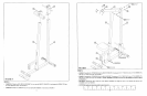
STEP
3:
• Insert two 3 X 2" GUIDES (21) into the ends
of
the ROLLER PAD SUPPORT (6) as shown
in
FIGURE
3.
• Assemble two ROLLER PADS (11) to the ROLLER PAD SUPPORT (6) using two STARLOCK COLLARS (23).
•
SECURELY
assemble one SPRING PIN ASSEMBLY (35) to the spring pin barrel on the ROLLER PAD SUPPORT (6). See
FIGURE
3.
,~.-
---------------------------------------