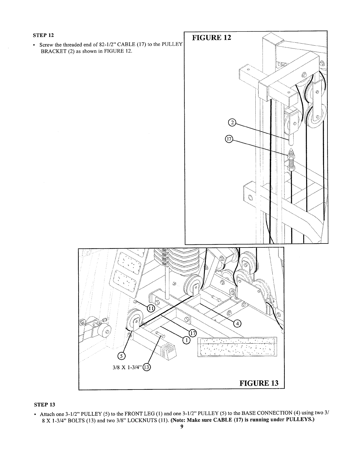
STEP 12
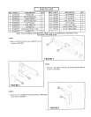
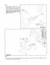
¯ Screw the threaded end of 82-1/2" CABLE (17) to the PULLEY
BRACKET (2) as shown in FIGURE 12.
FIGURE 12
3/8 X 1-3/4"
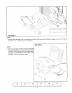
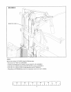
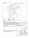
FIGURE ]13
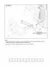
STEP 13
¯ Attach one 3-1/2" PULLEY (5) to the FRONT LEG (1) and one 3-1/2" PULLEY (5) to the BASE CONNECI’ION (4) using
8 X 1-3/4" BOLTS (13) and two 3/8" LOCKNUTS (11). (Note: Make sure CABLE (17) is running utnder PULLEYS.)
9


