6
1.
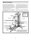
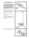
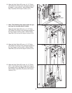
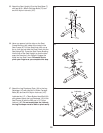
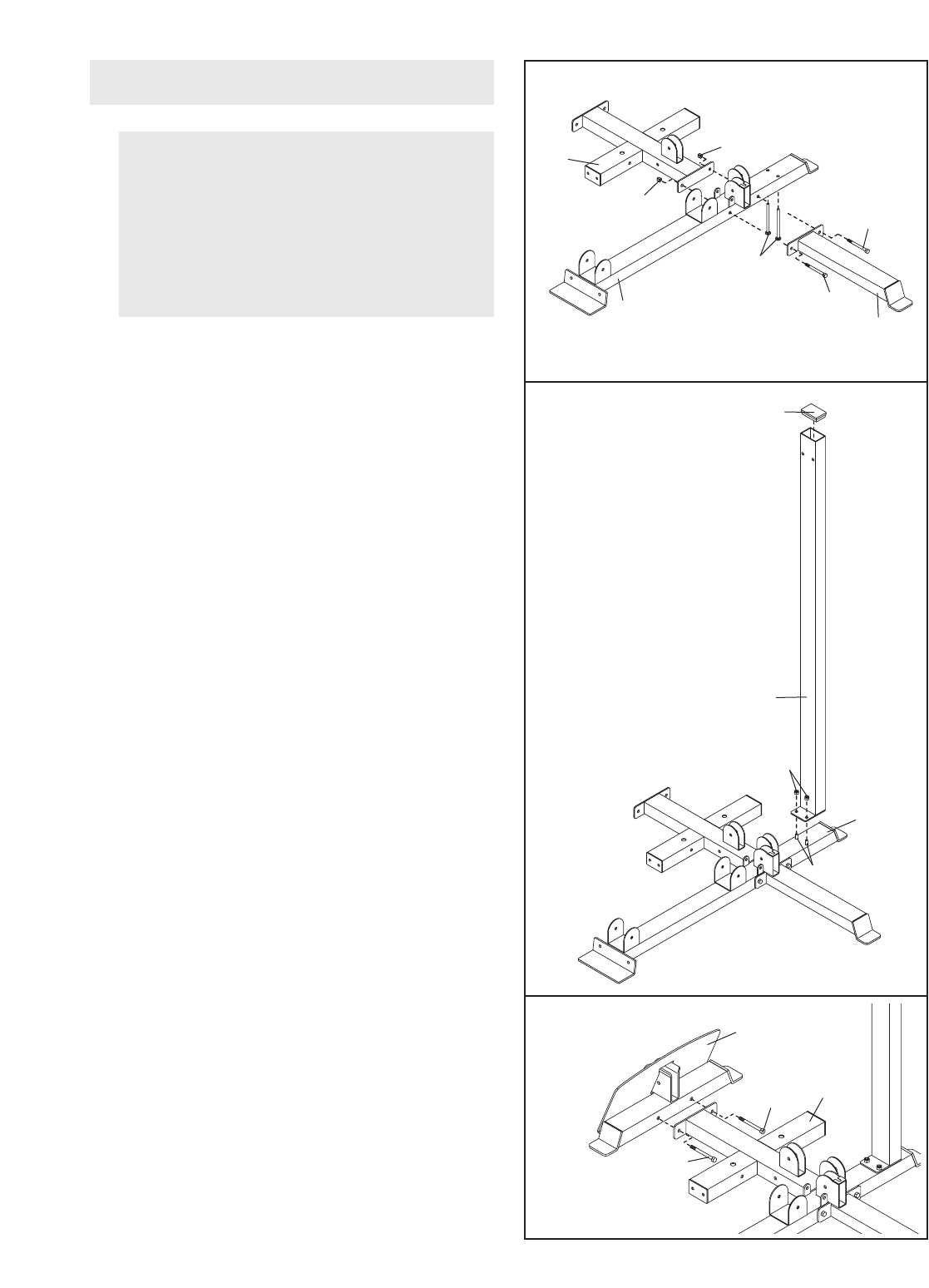
Attach the Weight Base (2) and the Stabilizer (96)
to the Base (1) with two M10 x 96mm Button
Head Bolts (77) and two M10 Nylon Locknuts
(101). Do not tighten the Locknuts yet.
Insert two M10 x 68mm Carriage Bolts (73) into
the Base (1).
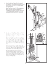
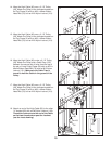
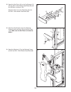
2. Press a 50mm x 76mm Inner Cap (52) into the
top of the Upright (4).
Attach the Upright (4) to the Base (1) with the two
M10 x 68mm Carriage Bolts (73) and two M10
Nylon Locknuts (101). Do not tighten the
Locknuts yet.
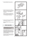
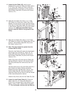
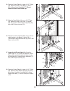
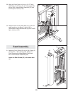
3. Attach the Foot Plate (3) to the Weight Base (2)
with two M10 x 92mm Button Head Bolts (90).
Before beginning, read the information on
page 5. This brief introduction will save you
much more time than it takes to read it.
To help you identify the small parts used in
assembly, we have included a PART IDEN-
TIFICATION CHART in the center of this
manual.
Frame Assembly
1
1
2
96
73
73
3
52
4
101
1
77
77
101
101
2
3
90
90
2


