


26
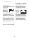
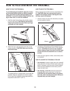
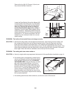
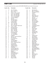
Remove the four #8 x 3/4" Screws (14) and care-
fully remove the Motor Hood (61).
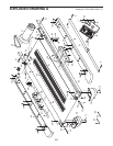
Locate the Reed Switch (44) and the Magnet (43)
on the left side of the Pulley (42). Turn the Pulley
until the Magnet is aligned with the Reed Switch.
Make sure that the gap between the Magnet
and the Reed Switch is about 1/8 in. (3 mm). If
necessary, move the Reed Switch slightly using a
slotted screwdriver. Reattach the Motor Hood (not
shown) with the four #8 x 3/4" Screws (not shown)
and two #8 x 1 1/2" Screws (not shown). Run the
treadmill for a few minutes to check for a correct
speed reading.
PROBLEM: The incline of the treadmill does not change correctly
SOLUTION: a. Hold down the Stop button and the Speed increase button, insert the key into the console, and
then release the Stop button and the Speed increase button. Press the Stop button and then
press the Incline increase or decrease button. The treadmill will automatically rise to the maxi-
mum incline level and then return to the minimum level. This will recalibrate the incline system. If the
incline does not calibrate, press the Stop button, and then press the Incline increase or decrease
button again. When the incline is calibrated, remove the key from the console.
PROBLEM: The walking belt slows when walked on
SOLUTION: a. Use only a single-outlet surge suppressor that meets all of the specifications described on page 14.
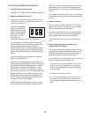
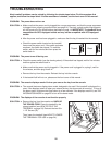
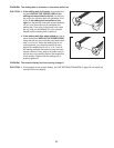
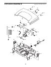
b. If the walking belt is overtightened, treadmill perfor-
mance may decrease and the walking belt may be-
come damaged. Remove the key and UNPLUG
THE POWER CORD. Using the hex key, turn both
idler roller bolts counterclockwise, 1/4 of a turn.
When the walking belt is properly tightened, you
should be able to lift each edge of the walking belt
2 to 3 in. (5 to 7 cm) off the walking platform. Be
careful to keep the walking belt centered. Then,
plug in the power cord, insert the key, and run the
treadmill for a few minutes. Repeat until the walking
belt is properly tightened.
c. If the walking belt still slows when walked on, see the front cover of this manual.
Top
View
43
44
1/8 in.
42
Idler Roller Bolts
2–3 in.
b
6
1
14