


Silver Strike Bowling™ Version 08/04 Page 43
© Copyright 2004 Incredible Technologies, Inc. All Rights Reserved. Unauthorized duplication is a violation of applicable law.
All other marks are the properties of their respective owners. All rights reserved.
APPENDIX B
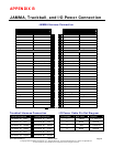
JAMMA, Trackball, and I/O Power Connection
JAMMA Harness Connection
SOLDER SIDE PARTS SIDE
WIRE COLOR FUNCTION FUNCTION WIRE COLOR
Black * A 1 * Black
Black * B 2 * Black
Red * C 3 * Red
Red * D 4 * Red
E 5
Orange * F 6 * Orange
KEY H 7 KEY
Count 2 J 8 Coin Counter Red-Green
K 9
Yellow-Green Left Speaker (-) L 10 Left Speaker (+) Yellow-Red
White-Green Right Speaker (-) M 11 Right Speaker (+) White-Red
Green-Black Video Green N 12 Video Red Red-Black
White Video Sync P 13 Video Blue Blue-Black
R 14 Video GND White-Black
S 15 Test Blue
Green-Blue Coin 2 T 16 Coin1 Red-Blue
U 17 Start 1 Red-White
V 18
W 19
X 20 Player 1 – Ball Weight Purple-White
Y 21 Player 1 – Overhead Violet-White
Z 22 Player 1 – Left Brown-White
A 23 Player 1 – Right Yellow-White
Orange-Yellow Volume Down B 24 Volume Up Orange-White
C 25 Coin 3 (Bill) Gray-White
D 26
Black GND E 27 GND Black
Black GND F 28 GND Black
*NOTE: Power is NOT routed through the JAMMA connector.
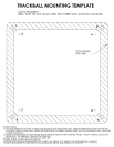
Trackball Harness Connection I/O Power Cable Pin Out Diagram
I/O Board Connector Trackball Connector Pin Number Wire Color Function
PIN WIRE #6 - Black PIN WIRE #1 – Black 1 Yellow + 12 Volts DC
PIN WIRE #1 - Red
PIN WIRE #2 – Red 2 Black Ground
PIN WIRE #2 - Yellow
PIN WIRE #3 – Yellow
3 Red + 5 Volts DC
PIN WIRE #3 - Green
PIN WIRE #4 – Green 4 Black Ground
PIN WIRE #5 - Blue
PIN WIRE #5 – Blue
PIN WIRE #4 - Purple PIN WIRE #6 – Purple