


Silver Strike Bowling™ Version 08/04 Page 8
© Copyright 2004 Incredible Technologies, Inc. All Rights Reserved. Unauthorized duplication is a violation of applicable law.
All other marks are the properties of their respective owners. All rights reserved.
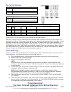
Power Cable, I/O Board Pin Out
Pin Number Wire Color Function
1 Yellow + 12 Volts DC
2 Black Ground
3 Red + 5 Volts DC
4 Black Ground
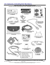
Game Electronics
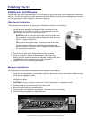
I/O Board Installation
NOTE: Before installing any electronics make sure cabinet power switch is in the OFF position and the cabinet
power is unplugged from the wall.
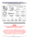
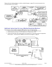
Silver Strike Bowling comes with a specially designed I/O board that works with your cabinet's already installed
JAMMA harness. The I/O board is used as a connection interface between the JAMMA and the Nighthawk
Chassis. Refer to the diagram on page 9.
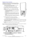
1. Mount the I/O board into the cabinet using 6 of the 6 x ¾" Hex Washer Head Sheet Metal Screws. The
existing JAMMA harness edge connector will attach to this board.
2. Cable connections:
q JAMMA Connector. Be sure it fits tightly.
q Trackball Cable to the Trackball connector. Other end will connect to the trackball.
q Power cable to the power input connector. Use the end with the 4-pin pigtail. Other end connects to
the Nighthawk Chassis.
q USB cable to the USB port. Other end connects to the Nighthawk Chassis.
q Audio Cables to the I/O board audio inputs. Other ends will connect to the Nighthawk Chassis.
q Video cable (SVGA) in from Nighthawk Chassis. Low or medium resolution monitors only. See
diagram on page 9. VGA or SVGA monitors are connected directly to the Nighthawk Chassis video
output. See diagram page 45.
3. Coin door wiring. Note: There is no power source at the JAMMA connector. Power for coin door lights can
be sourced at the Power Cable pigtail.
q Wire ground and appropriate power to the coin door lights. Depends on type of bulbs in your cabinet.
q Coin input switches and bill acceptor common ground wired from JAMMA ground. See pin out
diagram on page 43.
q Coin input signal wires to coin switches normally open post and bill acceptor signal out. See pin out
diagram on page 43.
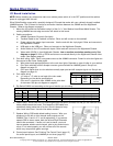
4. Coin meter wiring.
q +12 volts or + 5 volts to one lead of the coin meter.
Depending on the device specifications.
q Coin count 1 signal wire from JAMMA to the other lead
of the meter. See pin out diagram on page 43.
5. Dip Switch SW201 set according to the type of monitor you are using.
6. Cable Clamp. Mount near the I/O board aligned with the power connector so that you can have the USB
cable pulled towards the board. This keeps the USB cable from
accidentally being jostled out of its slot. Use this clamp to keep
other loose wires neat. Use wire ties where needed.
7. Speaker Wiring. SSB audio default setting is mono. Wire your
speaker(s) to the left or right channel audio outputs on the
JAMMA, Pins 10 and J or 11 and K respectively. If you want to
operate SSB in stereo mode, both the left and Right Channels
need to be connected. If audio out is set to stereo, you must
have a speaker wired to each channel, plus to plus and minus to
minus. If not wired properly you will not hear all of the sounds
which may compromise game earnings.
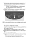
8. Control panel buttons. See Finishing The Control Panel (page 13)
for control panel layout, and JAMMA pin out chart (page 43).
SW201 Video Dipswitch Settings 0 = OFF 1 = ON
Position
4 3 2 1
Video
Mode
Resolution Scan Rate Monitor Video connection
0 0 0 1 1 640 X 480 31.5 KHz VGA Direct from Chassis, See Diagram on Page 45
0 0 1 0 2 800 X 600 37.8 KHz SVGA Direct from Chassis, See Diagram on Page 45
0 1 0 0 4 340 X 255 15.75 KHz Low Resolution Through I/O board, See Diagram on Page 45
0 1 0 1 5 512 X 384 25 KHz Medium Resolution Through I/O board, See Diagram on Page 45