Silver Strike Bowling™ Version 08/04 Page 19
© Copyright 2004 Incredible Technologies, Inc. All Rights Reserved. Unauthorized duplication is a violation of applicable law.
All other marks are the properties of their respective owners. All rights reserved.
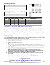
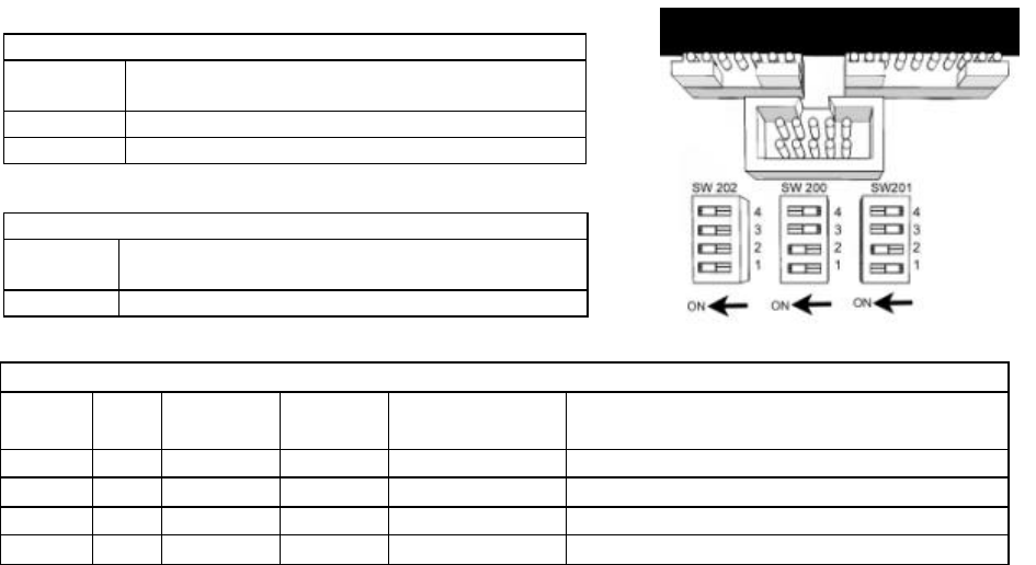
Dip Switch Settings
SW202 Dip Switch Settings 0 = OFF 1 = ON
Positions
4 3 2 1
Function
0 0 0 0 Default
1 0 0 0 Enter Operator Mode Menus
Initial Power-Up
There are several steps you should take when powering up your Silver Strike Bowling for the first time. This is a
quick checklist for you to follow when doing your first initial power-up:
q Plug in the game and turn it ON; be sure the game powers up correctly into the attract mode.
q Adjust volume levels to desired settings.
q Adjust monitor settings for best picture.
NOTE:
Sound and Video Tests are available through the System Tests Menu. They are beneficial when making
any adjustments. (See System Tests Menu on page 26). Proper monitor and sound adjustment is very
important.
q Try all money slots. Drop quarters or tokens through to check the coin mechs and insert a bill into the
bill acceptor. Make sure the game is adding credits.
q Test all of the player input controls. You can use the PLAYER CONTROL TESTS in the SYSTEM
TESTS MENU.
q Upon initial power-up the game is set to factory default settings. These settings affect game elements
such as number of credits per coin, difficulty settings, etc. The OPERATOR MENUS section (see page
21) will describe how to alter these settings for your location.
Congratulations! Your Silver Strike Bowling is ready for play!
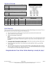
SW200 Dip Switch Settings 0 = OFF 1 = ON
Position
4 3 2 1
Function
1 1 1 1 Default - Switch Is Not Used
SW201 Video Dipswitch Settings 0 = OFF 1 = ON
Position
4 3 2 1
Video
Mode
Resolution
Scan Rate
Monitor Video connection
0 0 0 1
1 640 X 480 31.5 KHz VGA Direct from Chassis, See Diagram on Page 45
0 0 1 0
2 800 X 600 37.8 KHz SVGA Direct from Chassis, See Diagram on Page 45
0 1 0 0
4 340 X 255 15.75 KHz
Low Resolution Through I/O board, See Diagram on Page 45
0 1 0 1
5 512 X 384 25 KHz Medium Resolution
Through I/O board, See Diagram on Page 45


