


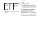
The A1 and A2 values are entered with their respective signs.
If the ER "0" value is other than zero, the respective correction is
to be taken into account while operating the range finder. The
error value is subtracted from the elevation measurement, if the
latter is positive, and added, if it is negative.
7.6.2. To check compass, set up the AI for operation. Then,
check the sensitivity and balance the needle.
For the purpose proceed as follows:
- Level the AI;
- Release the needle;
- Unbalance the needle by using a knife or a screwdriver.
To make sure that the needle is free from defects, check that:
- The needle oscillates in a smooth and uniform manner to
regain balance;
- The position of the needle end is the same as the mark when
the needle settles;
- The needle ends are leveled with the marked plates within ±
0.5 mm.
The compass requires triple checking. If even a single
requirement is not satisfied, the AI needs repair.
7.7. After the rangefinder check is complete, set the ON-OFF
and ILLUM. selector switches to the OFF position.
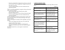
- Mark numbers of the plotting board with respect to the
selected scale ( 1:25, 000 or 1:50,000) and the reference
point, observation post and target location;
- Read the rectangular coordinates of the reference point from
the map and note them down on the plotting board or card;
- Align the circular scale zero of the plotting board with the
zero wheel;
- Use the reference grid of the plotting board to plot the
reference point on the circular scale in accordance with the
map coordinates;
- Set the circular scale of the board to read the directional
angle as determined for the reference point from the
observation post;
- Draw a vertical line from top downwards through the
reference point marked on the circular scale. See that the line
is parallel with the grid lines;
- Use the rule to lay off the OP-to-reference point range on the
drawn line. Mark the obtained OP location point on the
circular scale;
- Adjust the circular to read the directional angle as
determined for the target from the observation post;
- Pass a vertical line from bottom upward through the OP
point in parallel with the grid lines on the circular scale;
- Use the rule to lay off the OP- to-target range on the drawn
line. Mark the target location with a dot and symbol;
- Setting the circular scale to zero, read the target and OP
rectangular coordinates off the board. Note down the
coordinates on the board or card;