


Plot the target on the map using the obtained rectangular
coordinates.
8.9. When using the rangefinder under the conditions of
insufficient light, set the ILLUM. selector switch to ON.
8.10. If a target is located against an intense background (bright
sky, sunlit snow or sand, etc.), the range display may indicate as
if more than one target is caught in the beam, and the range
indications may differ every time that MEASURE L button is
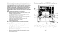
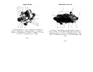
depressed. To eliminate the adverse background effects, the
frame of the binocular objective lens should be fitted with the
diaphragm 22 (Fig. 6) and secured by means of a pin and rubber
clamp on the case.
Don’t use the diaphragm in low temperatures, in mist and limited
visibility conditions.
When using the compass to orient the rangefinder, keep in mind
that the indexing accuracy of the magnetic needle is affected by
the nearby iron or steel objects. The motor vehicles and similar
massive objects must be at least 10 m away, medium-size objects
(hammers, pliers, similar tools) must be at least 0.5 m away, and
small-size things (flashlights, knife, screwdriver, etc.) must be 20
cm away from the unit.
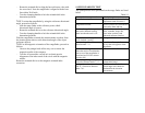
7.6. To check the range finder for proper operation when using
the AI and the tripod:
- Check the AI zero elevation reference (ER "0");
- Check the AI compass.
ER "0" is the setting of the elevation scale that corresponds to
the horizontal position of the range finder Binocular axis.
7.6.1. To check the zero elevation reference, proceed as follows:
- Stick a pole at 50 to 100 m away from the unit and mark it
with the rangefinder objective height above the ground level;
- Aim the reticle crosshair to the mark and read the tilt angle
(A1);
- swap the rangefinder and the pole positions, and apply
another mark to the pole in accordance with the new height
of the rangefinder objective;
- Aim the crosshair to the new mark of the pole and read again
the tilt angle (A2);
- find the ER "0" from the formula:
A1 + A2
ER "0" = ———— ,
2