


- remove the moist silica gel from the case and fill the case with
the fresh one.
Moist silica gel may be subjected to multiple dehydrations at
(120±3) °C without any deterioration of its properties. Using a
microwave oven is allowed.
To dehydrate the silica gel, proceed as follows:
- place the silica gel in a clean metal vessel;
- place the vessel on the heat source providing heating up to
(120±3) °C. Measure the temperature directly on the silica gel;
- see the silica gel changing its colour.
The silica gel is dry and good for use when it turns bluish from
pink. When heating up, keep the silica gel away from open
flames.
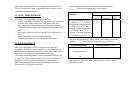
11. TROUBLESHOOTING
11.1. If the rangefinder or its components do not function
properly, first of all check that:
- the rangefinder is properly set up;
- the controls have been operated in the proper succession;
- the optical parts are free from dust, dirt and oil stains on the
exterior;
- the battery is charged.
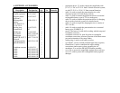
Connector X1 couples the controls and the Rechargeable
battery to control circuit board (A1).
C1 and C2 are energy storage capacitors placed in the pumping
circuit. They are charged up to 700-1000 V through a special
contact located on the control circuit board A1. Capacitor C3 and
diodes V1, V2 are placed in the pumping circuit to prevent RF
oscillations or reversal of the voltage polarity across capacitors
C1, C2. E1 is a pumping flashtube. Transformer T1 produces 10-
15 kV firing voltage pulses applied to tube E1. The primary
winding of the transformer is furnished with a negative voltage
of 130 to 185 V supplied from control circuit board A1. The
flashtube is externally ignited. The ignition voltage pulse is
conducted to the metal-clad envelope of the tube E1.
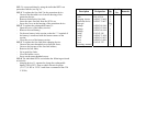
DCC, AC ckt, power supplies of the TIC, PhD assembly and
battery charge analyzer are mounted on board A1.
The counting-logic circuitry of the TIC and the TSGC of the
PhD assembly are located on counter circuit board (A3).
A2 is the information display assembly board. Arranged
thereon is the indicating circuit of the TIC: digital range
indicator, multiple target indicator, outgoing pulse absence
indicator, ranging readiness indicator (green) and battery
discharged condition indicator (red). Control signals and supply
voltages pass through display circuit board A2 from control
circuit board A1 to circuit board A3 and to the PhD assembly.
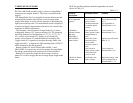
Circuit boards A1, A2 and A3 are connector-coupled with the
PhD assembly. Plug X2 couples the cable of the remote control
set to receive range data in binary code.