


6
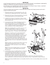
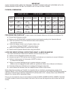
11. Slide the LEFT INSIDE HANDLEBAR SHROUD (5) near the
L
EFT UPRIGHT HANDLEBAR BRACKET (N).
Locate and position the LEFT OUTSIDE HANDLEBAR
SHROUD (7) to match the LEFT INSIDE HANDLEBAR
SHROUD.
Secure the SHROUDS together using three SCREWS
(15). Tighten the SCREWS securely. Do not overtight-
en the S
CREWS. Repeat the procedure for the RIGHT
INSIDE and OUTSIDE HANDLEBAR SHROUDS (6 & 8).
12. Locate the D
ISPLAY CONSOLE (9). Remove the eight
S
CREWS (P) from the back of the DISPLAY CONSOLE
and separate the front of the DISPLAY CONSOLE from
the rear. Position the REAR CONSOLE (Q) over the
LEFT and RIGHT TOP MOUNTING PLATES (H & J) as
shown. From the bottom of the L
EFT and RIGHT TOP
MOUNTING PLATES, secure the REAR CONSOLE using
four S
CREWS (17). Tighten the SCREWS securely. Do
not overtighten the SCREWS.
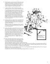
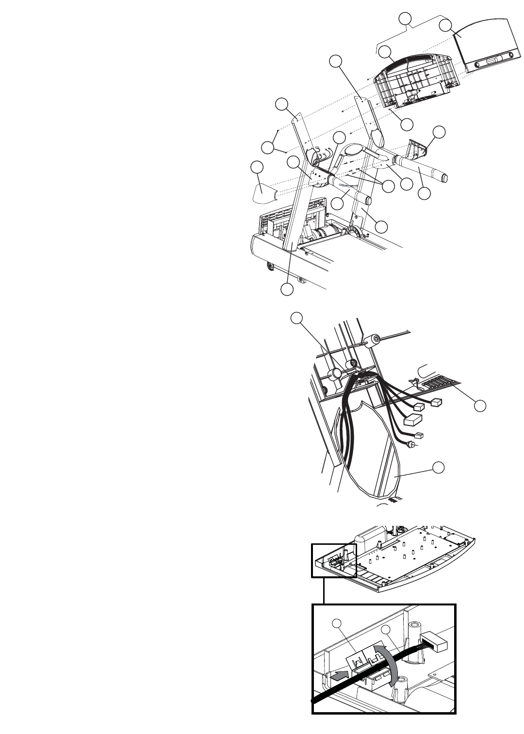
13. Position and rest the FRONT CONSOLE (R) face down
across the HANDLEBARS (3). Connect all CONNECTORS
leading from the LEFT (if equipped) and RIGHT
UPRIGHTS (1 & 2) to the corresponding CONNECTORS
located on the FRONT CONSOLE. Feed any excess
W
IRE HARNESS into the UPRIGHTS. Carefully route all
WIRE HARNESSES through the WIRE HARNESS GUIDES
(S) located at the lower left of the REAR CONSOLE
(Q).
Note: Consoles for the European Union countries
are equipped with a F
ERRITE (T). Open the FERRITE
(T). Route the MAIN WIRE HARNESS (G) through the
FERRITE. Close the FERRITE.
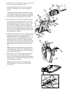
14. Tilt the FRONT CONSOLE (R) upright and in position
over the R
EAR CONSOLE (Q). Secure the FRONT
CONSOLE to the REAR using the previously removed
eight SCREWS (P). Tighten the SCREWS securely. Do
not overtighten the SCREWS.
Note: Be careful not to pinch any cables when
assembling the F
RONT CONSOLE (R) to the REAR
CONSOLE (Q).
S
1
Q
H
J
Q
R
9
7
1
2
3
8
P
3
N
6
5
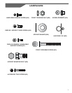
15
17
T
G