


9
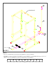
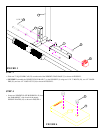
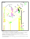
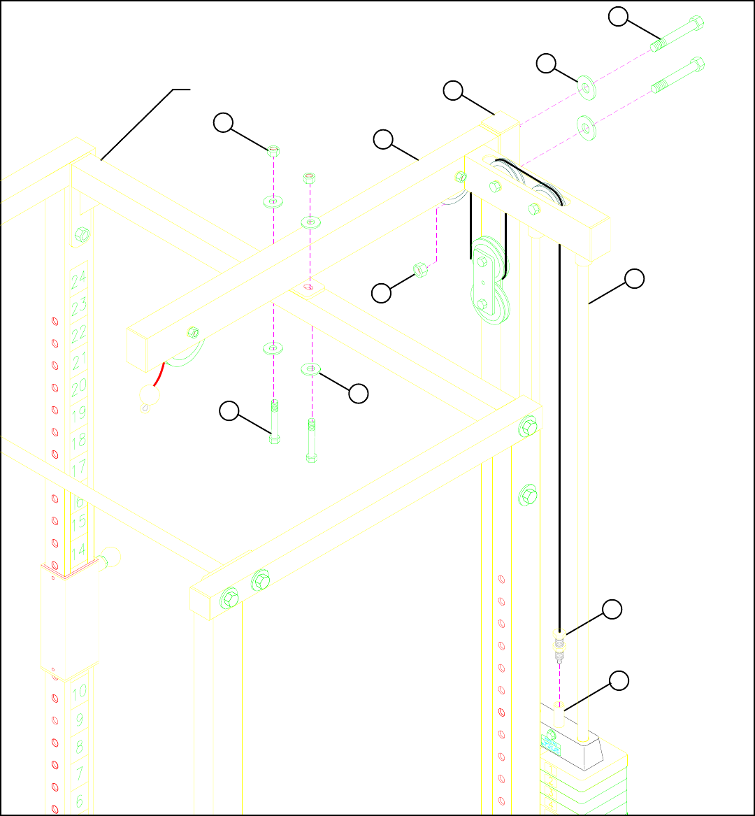
STEP 9:
FIGURE 9
• Swing the GUIDE RODS (9) under the TOP BOOM (2) as shown on FIGURE 9.
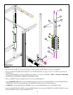
• Assemble the TOP BOOM (2) over the GUIDE RODS (9) and SECURELY assemble the TOP BOOM (2) to the UPRIGHT (1)
using two 1/2 X 3” BOLTS (28), two 1/2” WASHERS (29), and one 1/2” LOCK NUT (30). See FIGURE 9.
• SECURELY assemble the TOP BOOM (2) to the top of the POWER RACK using two 3/8 X 3” BOLTS (26), four 3/8” WASH-
ERS (31), and two 3/8” LOCK NUTS (32). See FIGURE 9.
• Screw the threaded end of the LAT CABLE (15) approximately 3/4” into the end of the WEIGHT STACK SHAFT (13) and tighten
jam nut securely. See FIGURE 9.
15
13
31
3/8 X 3” 26
1
2
32
9
1/2 X 3” 28
30
29
POWER RACK