


5
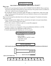
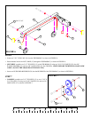
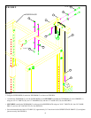
FIGURE 4
• Insert two WEIGHT PLATE BUSHINGS (42) into
the “PARABODY” side of each of the twenty
WEIGHT PLATES (43) as shown in FIGURE 4.
STEP 4
43
42
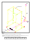
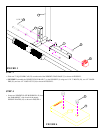
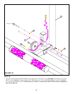
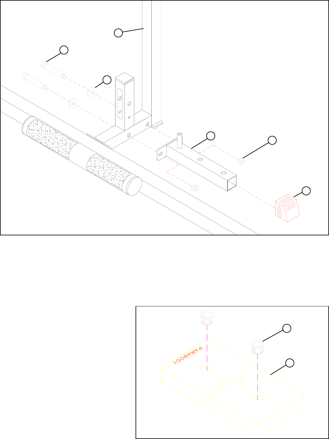
FIGURE 3
STEP 3
• Slide one 2” SQ. COVER CAP (22) over the end of the WEIGHT STACK BASE (7) as shown in FIGURE 3.
• SECURELY assemble the WEIGHT STACK BASE (7) to the UPRIGHT (1) using two 1/2 X 3” BOLTS (28), two 1/2” WASH-
ERS (29), and two 1/2” LOCK NUTS (30) as shown in FIGURE 3.
29
30
22
1/2 X 3” 28
7
1