


16
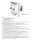
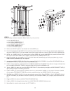
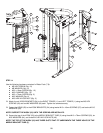
STEP 7:
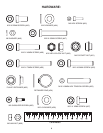
Use the following hardware contained in Blister Packs (7-3), (7-4) and (7-5):
M10 WASHER (Qty. 4)
M10 HEX NYLOCK NUT (Qty. 2)
M10 x 45mm SCREW (Qty. 2)
M10 SOCKET HEAD NUT (Qty. 2)
M10 x 50mm SCREW (Qty. 2)
PULLEY RETAINER (Qty. 2)
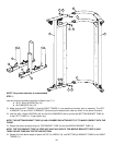
Remove the JAM NUT (59) from the threaded end of the CABLE (21).
Lower the threaded end of the CABLE (21) down the long vertical tube that is in front of the gym until it can be retrieved near
where the (LOWER) PULLEY (13) was located. Carefully pull enough cable out to reach the RIGHT ROLLER CARRIAGE (29).
INSTALL the (LOWER) PULLEY (13) using the M10 x 45mm SCREW (48), two M10 WASHERS (44), and M10 HEX NYLOCK
NUT (49). Be sure that the CABLE (21) is properly routed around the (LOWER) PULLEY (13).
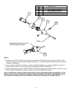
Bring the threaded end of the CABLE (21) up to the RIGHT ROLLER CARRIAGE (29) and thread the CABLE (21) into the
RIGHT ROLLER CARRIAGE (29). Do not tighten!
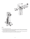
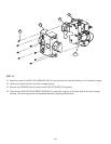
Assemble the (MIDDLE UPPER) PULLEY (13) by using two FULL PULLEY COVERS (14), one PULLEY RETAINER (53), one
M10 SOCKET HEAD NUT (51) and one M10 x 50mm SCREW (52).
Feed the cable end with the small ball between the MIDDLE UPPER PULLEY BRACKET (H) and then through the forward most
hole in the MIDDLE BRACKET TUBE (3) above the HEAD PLATE PULLEY ASSEMBLY (19).
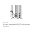
Take the CABLE (21) down and around the HEAD PLATE PULLEY (19) and back up through the MIDDLE BRACKET TUBE (3)
again, passing through the remaining access hole.
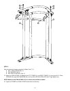
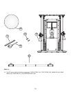
Feed the CABLE (21) around where the (UPPER) PULLEY (13) of the RIGHT TOWER (11) was located. Forward the CABLE
(21) through the TOP BRACKET TUBE (2) and out the access hole where the (UPPER) PULLEY (13) was located.
REINSTALL the (UPPER) PULLEY (13) using the previously removed M10 x 50mm SCREW (I), PULLEY RETAINER (J), M10
SOCKET HEAD NUT (K), and PARTIAL PULLEY COVER (L). Be sure that the CABLE (21) is properly routed around the PUL-
LEY.
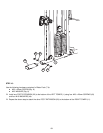
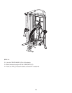
Bring the CABLE (21) down to the RIGHT ROLLER CARRIAGE (29).
Feed the CABLE (21) through the two pulleys in the RIGHT ROLLER CARRIAGE (29) as shown.
Repeat Step 6 to route the cable through the LEFT TOWER (1).
21
2
3
29
19
13
13
13
59
Lower Pulley
Upper Pulley
Middle Upper Pulley
27
53
38
14
53
52
51
27
13
51
14
13
H
Middle Upper Pulley
Upper Pulley