


11
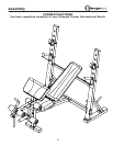
Assembly
NOTE
:
Hand tighten bolts and nylon nuts until machine is fully assembled.
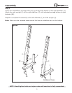
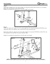
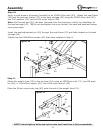
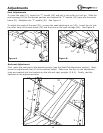
Step 10
Apply a small amount of grease (included) to an M10X145mm bolt (53). Attach the seat frame
(10) and the backrest frames (17) to the seat carriage (42) using the M10X145mm bolt (53),
two M10 washers (43), and an M10 nylon locknut (58).
Note: 1) The seat pad (21) has been removed from the drawing to clarify the installation to
the seat carriage (42). 2) Do not overtighten the nylon locknut, the seat and backrest frames
must pivot easily.
Insert the seat adjustment pin (40) through the seat frame (10) and tube located on the seat
carriage (42).
Tighten the four M6X40mm screws (48) that were installed in Step 9.
17
42
40
53
43
43
Grease
T ube
58
10
43
Figure 10
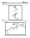
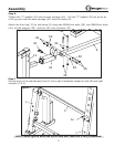
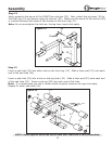
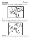
Step 11
Attach the weight tube (19) to the leg lever (18) using an M8X70mm bolt (71), two M8 wash-
ers (50), a 17mmX9mm spacer (61), and a M8 nylon locknut (49).
Place the 25mm round outer cap (62) onto the end of the weight tube (19).
50
19
1 8
62
7 1
61
5 0
49
Figure 11