Page 17
Step 5:
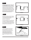
Step 3:
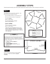
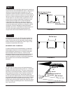
FIGURE 3
Support assembly
Slip joint
Slide in
Top rail w/sockets
FIGURE 4
Top rail
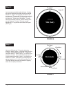
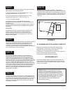
FIGURE 5
Hole
Pull with
spring pull tool
Top rail
"V" ring
Mat (bed)
Step 4:
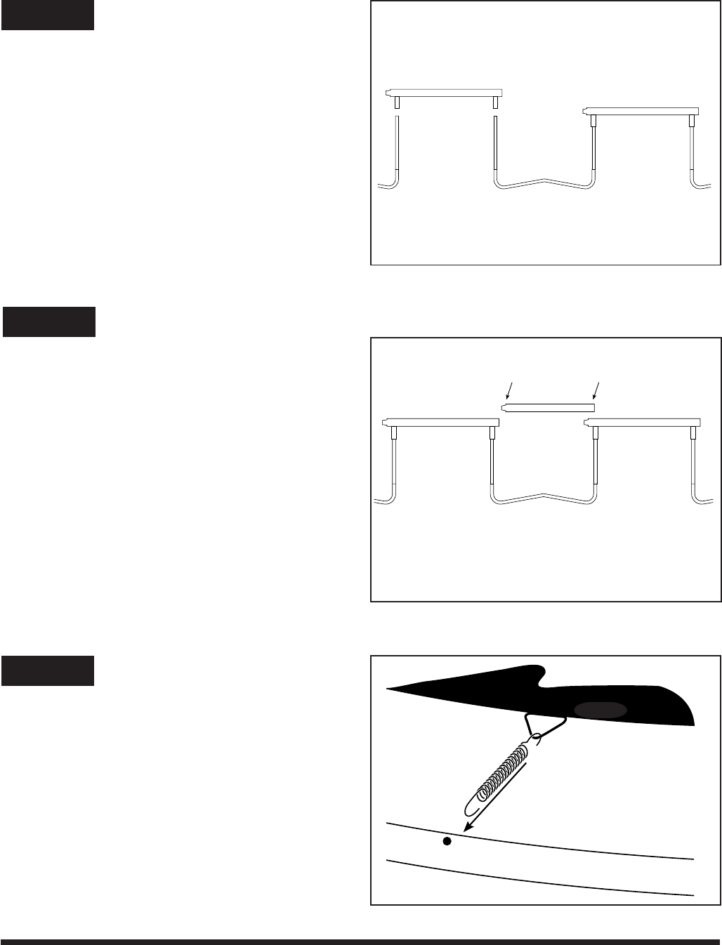
It is best to use a spring as a pull tool to pull and
attach the springs from the “V” ring on the bed
(mat) to the frame holes. Using your hand can
lead to getting “pinched” and also doesn’t properly
tension the spring. Attach the spring to the “V”
ring and using the “pull tool” spring, pull the
attachment spring to the frame by inter-connect-
ing spring hooks and pulling with one hand.
When the attachment spring hook reaches the
frame, use your other hand to push it into the
frame hole while disengaging the “pull tool” (See
Fig. 5).
Now install the remaining four (4) top rails in the gaps
between the four (4) top rails with sockets. Slide each
top rail into the joints at both ends of the gap (See Fig.
4). This completes the frame assembly.
MOVING the TRAMPOLINE
If you need to periodically move your trampoline all slip
joints should be secured with a weather resistant tape
(i.e. duct tape). This will keep the frame intact and
prevent the tubular elements from separating during the
move. The trampoline should be moved by at least two
people, kept horizontal, and lifted slightly. Disassemble
the trampoline for any other type movement.
At this point, you will need someone to assist you with
the next phase of the frame assembly. One person lifts
the support assembly shown in Fig. 2 (vertical leg
extensions, leg base) to a vertical position and inserts
the socket of a top rail with leg socket over the vertical
leg extension on one side. The other person then
similarly attaches an adjacent support assembly at the
other end of the top rail with leg sockets. You should
now have two support assemblies joined by a single top
rail with sockets. Each leg socket should have a vertical
leg extension inserted in it. Continue working sequen-
tially around the circle, connecting top rails with leg
sockets to support assemblies until this portion of the
frame assembly is free standing (See Fig. 3).


