


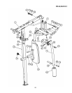
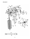
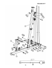
STEP 7 (See Diagram 7 & Cable Loop Diagram)
A.) Attach the 157” Lower Cable (#60) to the opening on the bottom of the Leg Developer
(#11).
B.) Attach a Pulley (#62) to the opening. Secure it with one M10 x 2 ½” Allen Bolt (#69),
two Ø 7/8” x Ø 5/8” Bushings (#44), and one M10 Aircraft Nut (#83).
C.) Draw the Cable underneath the Pulley to the open bracket on Base Frame (#5).
D.) Attach a Pulley to the bracket. Secure it with one M10 x 1 ¾” Allen Bolt (#71), two Ø
¾” Washers (#84), and one M10 Aircraft Nut (#83).
E.) Draw the Cable underneath the Pulley to the opening on the bottom of Front Vertical
Frame (#3). Attach a Pulley to the opening. Secure it with on M10 x 2 3/8” Allen Bolt
(#70), two Ø 7/8” x ½” Pulley Bushings (#45), and one M10 Aircraft Nut (#83).
F.) Draw the Cable underneath the Pulley then pull the Cable upward to the Angled
Floating Pulley Bracket (#25) previously installed in Step-6. Repeat D to install a
Pulley.
G.) Draw the Cable around the Pulley then downward to the opening on the Base Frame
(#5). Repeat B to install another Pulley.
H.) Pull the Cable around the Pulley then upward to the Double Floating Pulley Bracket
(#23) previously installed in Step-5. Repeat D to install a Pulley with a L-shaped
Cable Retainer. Adjust the Cable tension by adjusting this Pulley position on the
Brackets. If the tension is too tight then move the Pulley down by one hole. If the
tension is too loose then move up one hole.
I.) Draw the Cable around the Pulley then pull downward. Attach end of the Cable to a
bracket on the Base Frame. Secure it with one M10 x 1” Allen Bolt (#73), two Ø ¾”
Washers (#84), and one M10 Aircraft Nut (#83).
19