


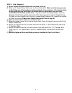
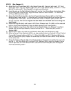
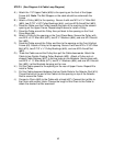
STEP 3 (See Diagram 3)
A.) Attach the Front Press Base (#6) to the Upper Frame (#4). Secure it with one 6 1/8” Front
Press Axle (#37), one Ø ¾” Washer (#84), one Ø ¾” Lock Washer (#88), one M10 x 1” Allen
Bolt (#73), and one Ø 2” End Cap (#47) on each end of the Axle.
B.) Insert the axle on the Right Butterfly Base (#7) into the Front Press Base from bottom. Slide
a Lock Ring (#52) onto the Axle. Align the holes. Secure it with one M6 x 1 ¾” Allen Bolt
(#77) and M6 Aircraft Nut (#89).
C.) Attach the Right Butterfly (#9) to the Front Press Adjustment Frame (#31) on the Right
Butterfly Base. Insert a M8 x ¾” Allen Bolt (#92) through Right Butterfly to the open track on
the Adjustment Frame (#31). Secure the Bolt with one Ø ½” Washer (#87) and one M6
Aircraft Nut (#89). Do not over tighten the Nut. Make sure the Bolt can travel along the
track freely.
D.) Rotate the Right Butterfly and thread a M18 Quick Release Lock Pin (#55) into the selected
hole on Front Press Adjustment Frame to obtain desired Front Press position.
E.) Slide a Butterfly Large Foam Roll (#63) onto the Right Butterfly arm. Attach a Front Press
Handle (#30) to the Right Butterfly. Secure it with a M10 x 1” Allen Bolt (#73) and Ø ¾”
Washer (#84).
F.) Repeat B to E above to install the Left Butterfly Base (#8) and Left Butterfly (#10).
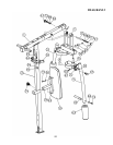
G.) Attach a Swivel Pulley Brackets (#26) to an open pulley bracket on the back of Front Vertical
Frame (#3). Secure it with one M10 x 2 ½” Allen Bolt (#69), two Ø ¾” Washers (#84), and
one M10 Aircraft Nut (#83). Repeat the same step to install the other Swivel Pulley Bracket
on the other side.
H.) Attach the Backrest Board (#39) to the Backrest Board Support Frame (#24). Secure it with
two M8 x 1 5/8” Allen Bolts (#75) and two Ø 5/8” Washers (#86). Insert the Support Frame
into the open slot on Front Vertical Frame. Use a M18 Lock Knob (#54) lock the Support
Frame at selected position.
11