


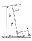
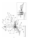
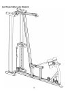
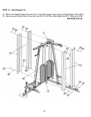
STEP 14 (See Diagram 14)
A.) Attach the end of the 103” Leg Press Cable (#47) to the bracket on the Leg Press
Frame (#36). Secure it with a M10 x 1 ¾” Allen Bolt (#94), two Ø ¾” Washers (#100),
and one M10 Aircraft Nut (#102).
B.) Draw the Cable to the first open bracket on the front of Left Base Frame (#32).
C.) Install a Pulley (#67) to the bracket with one M10 x 1 ¾” Allen Bolt (#93), two Ø ¾”
Washers (#100), and one M10 Aircraft Nut (#102).
D.) Draw the Cable to the opening on the bottom of Leg Press Frame. Install a Pulley to the
opening with one M10 x 2 5/8” Allen Bolt (#92), two Ø 7/8” x 5/8” Pulley Bushings (#5),
and one M10 Aircraft Nut (#102).
E.) Draw the Cable over the Pulley to the second open bracket on the Left Base Frame.
Repeat Procedure C above to install a Pulley.
F.) Draw the Cable underneath the Pulley then through the bottom of Left Seat Support
(#35) and Left Vertical Frame (#33) to the open bracket on the back of Left Base
Frame. Repeat Procedure C above to install a Pulley
G.) Draw the Cable around the Pulley then upward to the Single Floating Pulley Bracket
(#14) installed in Step-13.
H.) Connect the end of Cable to a Chain (#75) with a Hook (#76). Secure the Chain to the
Bracket with one M10 x 1” Allen Bolt (#94), two Ø ¾” Washers (#100), and one M10
Aircraft Nut (#102).
I.) Adjust the length of the Chain to adjust the tension of the Cable System.
30