


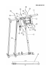
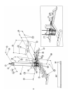
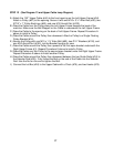
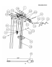
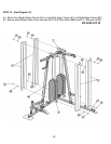
STEP 13 (See Diagram 13 and Upper Cable Loop Diagram)
A.) Attach the 130’” Upper Cable (#44) to the front opening on the Left Upper Frame (#34).
Attach a Pulley (#67) to the opening. Secure it with one M10 x 3 ½” Allen Bolt (#90), two
Ø 7/8” x 1” Pulley Bushings (#53), and one M10 Aircraft Nut (#102).
B.) Draw the Cable over the Pulley along the Left Upper Frame towards the back of the
machine. Make sure the Ball Stopper on the Cable is underneath the Left Upper Frame.
C.) Draw the Cable to the opening on the back of Left Upper Frame. Repeat Procedure A
above to install a Pulley.
D.) Draw the Cable around the Pulley then downward. Attach a Pulley to a Single Floating
Pulley Bracket (#14).
E.) Secure the Pulley with one M10 x 1 ¾” Allen Bolt (#93), two Ø ¾” Washers (#100), and
one M10 Aircraft Nut (#102). Let the Bracket hanging for now.
F.) Draw the Cable around the Pulley then upward to the first open bracket underneath the
Right Upper Frame (#1). Repeat Procedure E above to install a Pulley.
G.) Draw the Cable over the Pulley to the second open bracket under the Right Upper Frame.
Repeat Procedure E above to install another Pulley.
H.) Draw the Cable around the Pulley then downward between the two Guide Rods (#16) to
the Selector Rod (#28). Fully thread the Bolt on the end of the Cable into the Selector
Rod. Use the Nut on the end to tighten the Bolt.
I.) Connect the Lat Bar (#24) to the Upper Cable with a Chain (#75), and two Hooks (#76).
27