


30
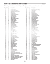
Part List—Model No. IMTL24490 R0899A
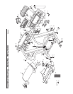
K
ey No. Qty. Description Key No. Qty. Description
1 2 Cushion Plate
2 4 Cushion Plate Screw
3 2 Adjustable Deck Cushion
4 2 Rod Screw
5 1 Cushion Rod
6 1 Cushion Knob Screw
7 1 Cushion Knob
8 2 Foot Rail Cover
9 1 Left Foot Rail
10 1 Left Foot Rail Endcap
11 2 Endcap Screw
12 15 Plastic Fastener
13
2 Front Isolator
14 2 Motor Mount Washer
15 32 3/4” Screw
16 2 Cushion Board
17 2 Platform Screw
18 2 Motor Star Washer
19 2 Rear Isolator
20 1 Catch
21 2 Belt Guide
22 1 Walking Platform
23 1 Walking Belt
24 1 Front Roller/Pulley
25 1 Magnet
26 4 Motor Mount Nut
27 1 Motor
28* 1 Motor Assembly
29 1 Front Roller Pulley
30 1 Motor Adjustment Bolt
31 1 Motor Plate
32 1 Motor Pivot Nut
33
1
Motor Mount Plate
34 4 Motor Isolator
35 4 Motor Bolt
36 2 Motor Mount Bolt
37
5 Frame Pivot Nut
38 2 Frame Spacer
39 1 Reed Switch Clip
40 1 Frame
41 5 Screw
42 2 Side Hood Mount
43 2 Front Hood Mount
44 1 Transformer
45 1 Bottom Incline Motor Bolt
46 4 Incline Motor Nut/Lift Frame Nut
47 1 Lift Frame
48 1 Right Foot Rail Endcap
49 5 Roller Adj. Washer/Latch Washer
50
3
Front Roller Nut/Cushion Nut
51
1 Incline Sensor Wire
52
1
Motor Belt
53 1 Right Frame Pivot Cap
54 1 Incline Motor
55 1 Controller
56 8 Base Pad
57 4 Wheel Spacer
58 4 Plastic Stand-Off
59 1 Power Board w/Clips
60 2 Caution Decal
61 8 Belly Pan Spacer
62 8 Belly Pan Screw
63 1 Sensor Unit
64 1 Right Rear Endcap
65 2 Endcap Washer
66 2 Endcap Screw
67 2 Frame Endcap
68 2 Rear Roller Adj. Bolt
69 1 Warning Decal
70 1 Belly Pan
71 1 Left Rear Endcap
72 1 Rear Roller
73 2 Frame Pivot Bolt
74 2 Frame Pivot Washer
75 1 Left Frame Pivot Cap
76 24 Small Screw
77 1 Motor Hood
78 2 4-pound Weight
79 1 Belly Pan
80 1 Power Cord
81 1 Power Cord Grommet
82 1 Circuit Breaker
83 1 On/Off Switch
84 2 Upright Endcap
85
1
Releasable Tie
86 1 Right Foot Rail
87 1 Tie Clamp
88 8 8” Cable Tie
89
1 Reed Switch/Sensor Wire
90 1 8” Green Ground Wire
91 2 Shock
92 1 Upright/Base
93 2 Lift Frame Bolt
94 2 Receiver Screw
95 1 Receiver
96* 1 Hand Pulse Sensor
97 1 Motor Pivot Bolt
98 2 Latch Bolt
99 1 Top Incline Motor Bolt
100 1 Lock Pin
101 1 Lock Pin Clip
102
1
Lock Pin Collar
103
1 Lock Pin Spring
104
1
Latch Bracket
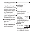
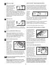
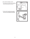
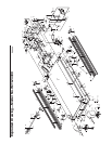
T
o find the parts listed below, refer to the
E
xploded Drawing
a
ttached in the center of this user’s manual.