


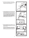
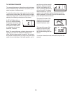
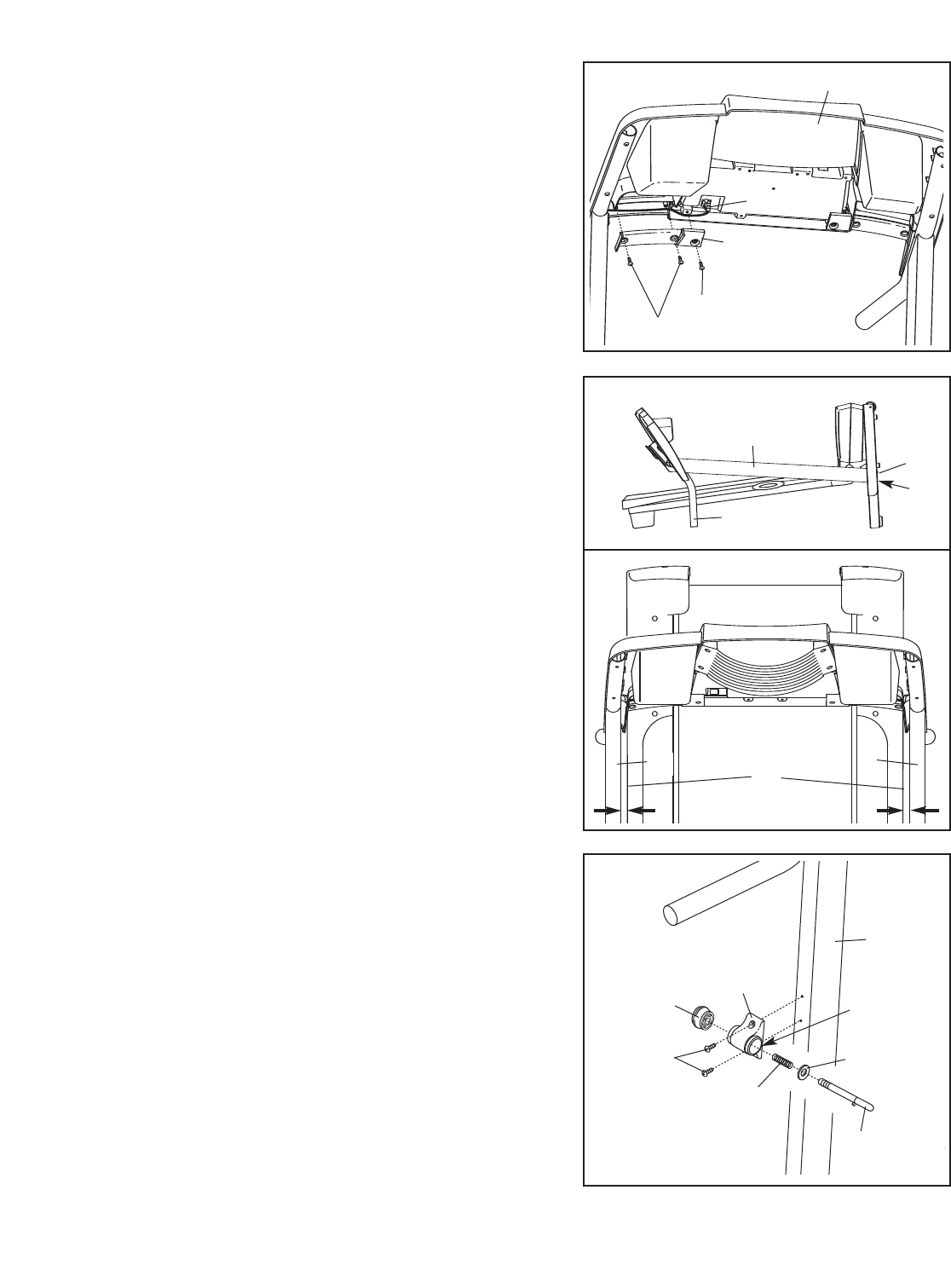
13. Attach the Latch Housing (29) to the Left Upright (7) with
two 3/4" Screws (2).
Make sure that the large hole in
the Latch Housing is on the side shown.
Remove the knob from the pin. Make sure that the col-
lar and the spring are on the pin as shown. Then, in-
sert the pin into the Latch Housing (29), and tighten the
knob back onto the pin.
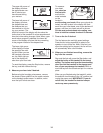
Plug in the power cord (see OPERATION
AND
AD-
JUSTMENT on page 11).
Next, change the incline of
the treadmill to the lowest level as described on
page 13. If you do not do this, the latch may not hold
the treadmill in the storage position.
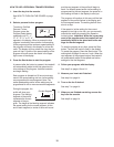
14.Make sure that all parts are properly tightened before you use the treadmill. Note: Extra hardware may
be included. Keep the included hex key in a secure place; the large hex key is used to adjust the walking belt
(see page 20). To protect the floor or carpet, place a mat under the treadmill.
Pin
Collar
Spring
Knob
7
29
2
13
Large
Hole
42
36
47
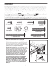
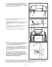
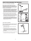
11. Cover the Upright Wire (42) with the Right Grip Plate
(36). Be careful not to pinch the Upright Wire. Tighten
t
wo 1/2" Screws (48) and a 3/4" Screw (2) into the Right
Grip Plate and the Console Base (47).
48
2
11
10
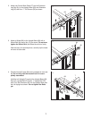
12. Carefully lower the Left and Right Handrails (71, 72)
until they are touching the floor.
See the lower drawing. Position the Uprights (7, 90) so
that the treadmill Frame (86) is centered between the
Uprights.
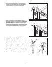
Firmly tighten the two 3" Upright Bolts (21) and the two
1" Upright Bolts (76) used in steps 1 and 4.
Raise the Uprights (7, 90) to the vertical position.
12
21
7, 90
71, 72
76
86
Top View
7
90