


308213 19
Service
Piston and Piston Rod Seals
NOTE: Air Motor Repair Kit 222958 is available. Parts
included in the kit are marked with an asterisk (*). For
the best results, use all the parts in the kit.
Disassembly
WARNING
To reduce the risk of serious injury whenever you
are instructed to relieve pressure, always follow the
Pressure Relief Procedure on page 10.
1. Stop the pump at the middle of its stroke. Relieve
the pressure before performing any service.
2. Follow the steps under Air Motor Shroud Disas-
sembly on page 11.
3. Disassemble the subplate and rocker assemblies,
as explained on page 17.
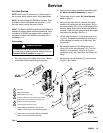
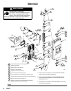
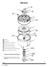
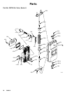
4. Remove the six screws (13), the lift ring (3), and
the o-ring (11*). See Fig. 10.
5. Using a 17 mm socket wrench, remove the fifteen
capscrews (12) holding the motor cap (2) to the
cylinder (1). Lift the motor cap off the cylinder.
Remove and inspect the o-ring (10).
6. Disconnect the air motor from the displacement
pump (see your separate pump manual). Leave
the adapter (R) attached to the piston rod.
7. Using a rubber mallet, drive the piston assembly
(5) out of the cylinder (1). Do not use a hammer.
8. Remove and inspect the piston o-ring (9*). Check
the piston and piston rod for scoring or damage.
Leave the piston rod and adapter (R) assembled
unless any of these parts requires replacement.
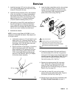
9. If it is necessary to disassemble the adapter (R)
from the piston rod, be careful not to scratch the
piston rod. Using adjustable wrenches on the flats
of the piston rod, unscrew it from the adapter (R).
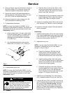
10. Remove the screws (14) and the bottom support
bracket (35). Press the bearing (6), o-ring (11*),
seal (7*) and wiper (8*) out the bottom of the
cylinder (1). Inspect these parts for wear or dam-
age.
11. Check the inner surface of the cylinder (1) for
scoring or other damage.
Reassembly
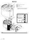
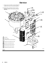
1. Lubricate the ID of the cylinder (1), using a rag
soaked in grease. See Fig. 10.
2. Lubricate the seals and o-ring (7*, 8*, 11*). The
bottom of the bearing (6) has a narrow o-ring
groove on the outer surface. Install the o-ring (11*)
in this groove. Install the wiper (8*) in the bearing,
so the notch of the wiper faces down, out of the
bearing. At the top of the bearing, install the seal
(7*) so the lips face up, toward the cylinder (1).
3. Press the bearing assembly into the neck of the
cylinder (1) from the bottom until it is seated.
4. Install the bottom support bracket (35). Apply
thread sealant to the screws (14) and torque to
6–7 NSm (55–65 in-lb).
5. If the adapter (R) was disassembled, screw the
piston rod onto the adapter (R). Using adjustable
wrenches on the flats of the piston rod, torque to
318–349 NSm (234–257 ft-lb).
6. Lubricate the o-ring (9*) and install it on the piston
(5).
7. Lubricate the piston rod. Lower the piston assem-
bly into the cylinder (1), carefully sliding the adapt-
er and rod down through the bearing (6).
8. Reconnect the air motor to the displacement pump
(see your separate pump manual).
9. Lubricate the o-ring (10) and install it on the motor
cap (2). Place the motor cap on the cylinder (1) so
the push rod hole (M) is aligned with the flat sur-
face (F) of the cylinder. Attach the cap with the
fifteen capscrews (12), using a 17 mm socket
wrench. Torque to 39–43 NSm (29–32 ft-lb).
10. Lubricate the o-ring (11*) and install it on the
underside of the lift ring (3). Align the lift ring with
the six inner holes in the motor cap, with the
grounding lug (49) positioned as shown. Apply
thread sealant and install the six screws (13).
11. Reassemble the subplate and rocker assemblies,
as explained on page 17.
12. Follow the steps under Air Motor Shroud Reas-
sembly on page 11.