


308213 15
Service
5. Install the bearings (107}) on the valve carriage
(111). Apply thread sealant and torque the screws
(104) to 2–3 NSm (20–30 in-lb).
6. Install the bearing retainers (122) in the recesses
of the valve carriage (111). Apply thread sealant
and torque the screws (104) to 9 NSm (75 in-lb).
Lubricate the pins (123n) and install them in the
bearing rollers (121n). Lubricate the retainers
(122) and install the bearing rollers (121n).
7. Lubricate the o-rings (120{) and install them on
the valve carriage (111). Snap the slide blocks
(119) in place with the lip (K) facing toward the
nearest end of the carriage. Be sure the o-rings do
not roll out or twist. Lubricate the slide blocks.
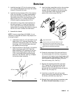
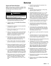
8. Assemble the detents.
NOTE: If you are using Detent Kit 222982, it is not
necessary to assemble the detents. Skip steps a and
b, and go to step 9.
a. Lubricate the roller pin (117) and install it in the
detent roller (115). Lubricate the spring (112)
and install in the plunger guide (113). Lubricate
the plunger (114). Push the detent roller and
pin assembly into the plunger.
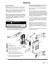
b. Align the windows in the plunger (114) with the
tabs of the plunger guide (113). Stand the
detent assembly on the workbench and push
down on the plunger guide to seat the roller
(115) in the plunger. Make sure the plunger
tabs lock in the windows. See Fig. 6. Repeat
for the other detent assembly.
Fig. 6
02249
115
114
113
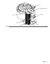
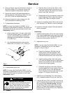
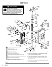
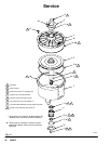
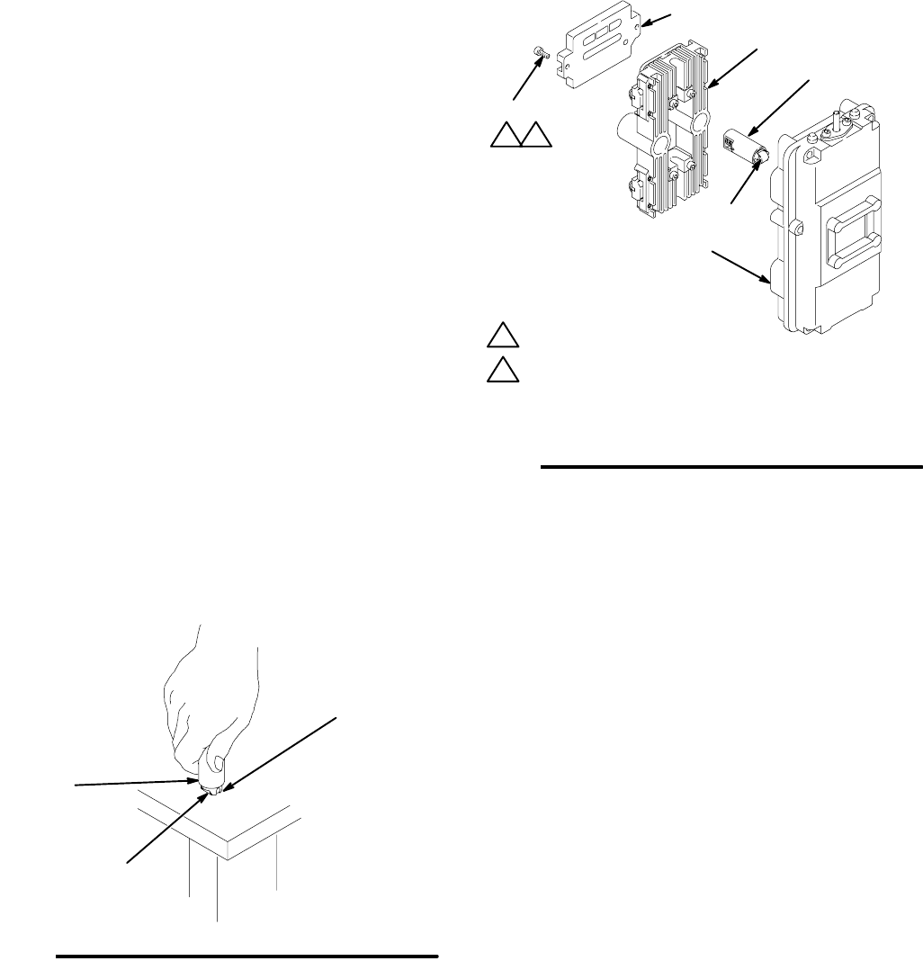
9. Insert the detent assemblies into the valve carriage
(111) so the detent rollers (115) face out of the
carriage. Set the carriage into the valve housing
(101) so the detent rollers engage the detent
plates (105) on the housing. See Fig. 7.
02269
Fig. 7
111
101
Jn
124
104
2
4
Torque to 9 NSm (75 in-lb) and unscrew as need-
ed for plate (124) to be flush with housing (101).
Apply thread sealant.
n These parts are included in Detent Kit 222982,
which may be purchased separately.
2 4
115
10. Grease the slide plates (124) and install them in
the valve housing (101), with the o-ring grooves
facing out of the housing. Apply thread sealant and
torque the screws (104) evenly to 9 NSm (75 in-lb),
then unscrew as needed for plates (124) to be
flush with housing (101). See Fig. 7
11. Replace the subplate gasket (26{) and seals
(27{). Grease the o-ring grooves of the slide
plates (G), then install the seals (27{) in the
grooves with the curved sides facing out (see the
Detail in Fig. 3 on page 12).
12. Install the air valve (25), using a 6 mm allen
wrench and the six socket screws (28). Torque to
22–23 NSm (195–205 in-lb). See Fig. 3.
13. Reinstall the air motor shroud as described under
Air Motor Shroud Reassembly, on page 11.